Environmental Engineering Reference
In-Depth Information
18.5.3 Loading Performance in the Grid-connected Mode
In the grid-connected mode, the active power
P
was set to 100 W and the reactive power was
set at 0 Var. The resistive, non-linear and unbalanced loads used in the stand-alone mode were
used again. The real power, less what was taken by the local load, was fed to the grid.
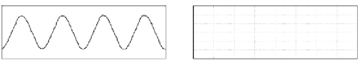
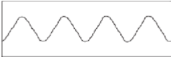
18.5.3.1 With a Balanced Linear Load
The output voltage
u
A
, the load current, the inverter current
i
A
and the grid output current
i
a
are shown in Figure 18.11. The spectra of output voltage
u
A
and the grid output current
i
a
are shown in Figures 18.11(e) and 18.11(f) respectively. The output voltage was of very good
quality but the current sent to the grid was distorted, so was the inverter output current. The
recorded local load voltage THD was 1
.
62% while the grid voltage THD was 1
.
15% and the
grid output current THD was 5
66%. The quality of the local load voltage was maintained
well but the quality of the current fed to the grid was not very good, with significant 3rd and
5th harmonic components.
.
18.5.3.2 With a Non-linear Load
The output voltage
u
A
, the load current, the inverter current
i
A
and the grid output current
i
a
are shown in Figure 18.12. The spectra of output voltage
u
A
and the grid output
6
6
i
A
i
A
−i
a
4
4
2
2
0
0
−2
−2
−4
−4
−6
−6
0
0.01
0.02
0.03
0.04
0.05
0.06
0.07
0.08
0
0.01
0.02
0.03
0.04
0.05
0.06
0.07
0.08
Time [s]
Time [s]
(a) Inverter current
(b) Phase
load current
30
6
u
A
i
a
4
15
2
0
0
−2
−15
−4
−30
−6
0
0.01
0.02
0.03
0.04
0.05
0.06
0.07
0.08
0
0.01
0.02
0.03
0.04
0.05
0.06
0.07
0.08
Time [s]
Time [s]
(c) Local load voltage
(d) Grid output current
10
5
THD of i
a
=5.66%
THD of u
A
=1.62%
4
3
5
2
1
0
0
0
5
10
15
20
25
30
0
5
10
15
20
25
30
Harmonics order
Harmonics order
(e) Spectra of the local load voltage
(f) Spectra of the grid output current
Figure 18.11
Loading performance in the grid-connected mode with a resistive local load


Search WWH ::

Custom Search