Environmental Engineering Reference
In-Depth Information
˙
D
p
θ
r
-
θ
Reset
g
˙
p
θ
P
set
T
m
1
1
θ
θ
˙
Js
s
n
-
θ
c
T
e
Formulas
of
T
e
,
Q
,
e
Q
PWM
generation
e
-
M
f
i
f
Q
set
1
i
Ks
-
Amplitude
detection
v
D
q
fb
v
m
v
r
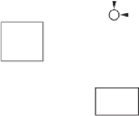
Figure 18.4
Electronic part of a synchronverter with the function of frequency and voltage control,
and real and reactive power regulation
nominal angular speed
˙
θ
n
, before feeding it into the damping block
D
p
; see the upper part of
Figure 18.4. As a result, the damping factor
D
p
actually plays the role of the frequency droop
coefficient, which is defined as the ratio of the required change of torque
T
to the change of
˙
θ
speed (frequency)
. That is,
˙
D
p
=
T
=
T
T
mn
θ
n
T
mn
˙
θ
n
,
˙
˙
θ
θ
where
T
mn
is the nominal mechanical torque. Note that in some references, e.g. (Sao and Lehn
2005),
D
p
is defined as
θ
T
. For example, it can be set for the torque (power) to change 100%
for a frequency change of 1%. The active torque
T
m
can be obtained from the set point of real
power
P
set
by dividing it with the nominal mechanical speed
˙
θ
n
p
. This completes the feedback
loop for real power; see the upper part of Figure 18.4. Because of the built-in frequency droop
mechanism, a synchronverter automatically shares the load with other inverters of the same
type and with SGs connected on the same bus. The power regulation loop is very simple,
because no mechanical devices are involved and no extra measurements are needed for real
power regulation (all the variables are available internally).
The regulation mechanism of the real power (torque) shown in the upper part of Figure 18.4
has a cascaded control structure, of which the inner loop is the frequency (speed) loop and the
outer loop is the real power (torque) loop. The time constant of the frequency loop is
J
τ
f
=
D
p
.
In other words,
J
can be chosen as
J
=
D
p
τ
f
.


Search WWH ::

Custom Search