Environmental Engineering Reference
In-Depth Information
v
s
v
o
0
π
2π
3π
4π
0
π
2π
3π
4π
ωt/rad
ωt/rad
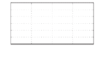
(a) Input and output voltages
(b) Line current
Figure 1.7
Phase-controlled rectifier operated in the inversion mode when
α
=
2
π/
3 with a negative
DC bus voltage present
input current
i
s
is positive. Hence, the energy (stored in the large inductor) flows backwards.
The DC output voltage is
2
√
2
π
α
+
π
√
2
V
s
sin
1
π
V
o
=
ω
t
d(
ω
t
)
=
V
s
cos
α,
α
which can be varied from
2
√
2
π
is changed from 0 to
2
.Ifthe
stored energy in the inductor is not enough to maintain a continuous current, then the current
becomes discontinuous and the thyristors turn off. It is worth noting that the circuit can be
operated in the inversion mode to feed energy to the grid if a negative voltage supply is present
on the DC bus. In this case,
V
s
to 0 when the firing angle
α
can be changed between
2
and
2
3
α
π
. The waveforms when
α
=
are shown in Figure 1.7.
For high power applications, three-phase bridge rectifiers with thyristors shown in Figure
1.8(a) are often adopted. The thyristors are fired at the firing angle
3.
When the firing signal is supplied to the corresponding thyristors that are forward biased, the
corresponding line-to-line voltage is passed to the load. The output voltage waveforms when
α
=
π/
α
with the interval of
π/
6 and
α
=
π/
2 are shown in Figures 1.8(b) and 1.8(c), respectively. The DC output
voltage is
3
√
6
π
α
+
2
√
2
√
3
V
s
sin(
+
6
)d(
1
π/
V
o
=
×
ω
ω
=
α
≈
.
α,
t
t
)
V
s
cos
2
34
V
s
cos
3
α
+
6
which can be varied from
3
√
6
π
is changed from 0 to
2
. Similarly,
when a negative DC voltage is present on the DC bus, the circuit can be operated in the inversion
mode to send energy to the grid, as shown in Figure 1.9.
V
s
to 0 when the firing angle
α
1.2.1.3 Diode Rectifiers Cascaded with a Boost Converter
The input currents of diode and phase-controlled rectifiers contain a significant amount of
harmonics, which causes a low power factor as well. In order to obtain a variable output


Search WWH ::

Custom Search