Environmental Engineering Reference
In-Depth Information
(
)
θ
=
0
a-
axis
i
a
a
Rotor field axis
θ
+
υ
a
R
s
, L
Rotation
-
M
M
R
f
,
L
f
i
f
+
N
f
Field voltage
u
f
R
s
, L
R
s
, L
-
f
′
-
υ
b
υ
c
+
+
c-
axis
b-
axis
i
b
M
i
c
c
b
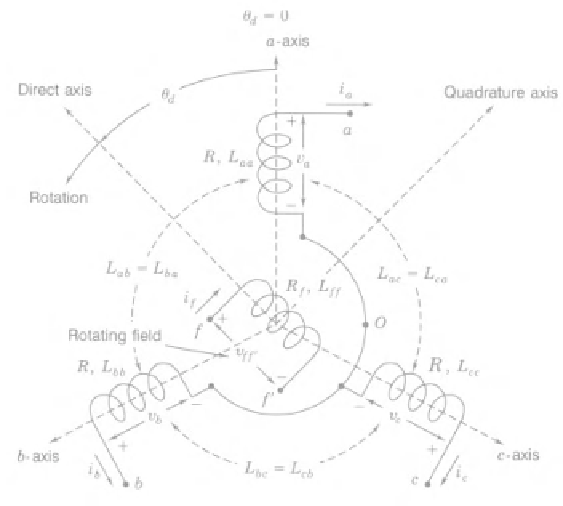
Figure 18.1
Structure of an idealised three-phase round-rotor synchronous generator with
p
=
1,
modified from Grainger and Stevenson 1994, Figure 3.4
where
i
a
,
i
b
and
i
c
are the stator phase currents and
i
f
is the rotor excitation current. Denote
⎡
⎤
⎡
⎤
a
b
c
i
a
i
b
i
c
⎣
⎦
,
⎣
⎦
=
i
=
and
⎡
⎣
⎤
⎦
,
sin
⎡
⎣
⎤
⎦
.
θ
cos
θ
−
θ
sin
θ
−
cos
sin
2
3
2
3
cos
θ
=
θ
=
cos
θ
−
4
3
sin
θ
−
4
3
Assume for the moment that the neutral line is not connected, then
i
a
+
i
b
+
i
c
=
0
.
It follows that the stator flux linkages can be rewritten as
=
L
s
i
+
M
f
i
f
cos
θ,
(18.1)


Search WWH ::

Custom Search