Environmental Engineering Reference
In-Depth Information
17.3.1 Steady-state Performance
17.3.1.1 Without a Local Load
In the steady state, the current reference
I
d
was set at 3 A. The reactive power was set at 0 Var
(
I
q
0). This corresponds to the unity power factor. Since there is no local load included in
the experiment, all generated active power was injected into the grid via a step-up transformer.
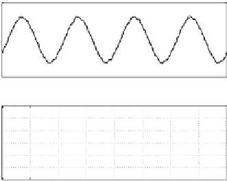
The output current
i
a
, reference current
i
ref
and the corresponding current tracking error
e
i
in the steady state are shown in the left column of Figure 17.3. The DB predictive controller
demonstrated very good tracking performance.
The current controllers discussed in Chapters 3 and 15-17 were compared and their cor-
responding values of THD of the grid current are listed in Table 17.1. It can be seen that the
current
H
∞
repetitive controller considerably outperformed the other controllers.
=
17.3.1.2 With a Resistive Load
In this experiment, a balanced resistive local load with
R
A
=
was connected
to the system. The grid output current reference
I
d
was set at 2 A (after connecting the inverter
to the grid) and the reactive power was set at 0 Var (
I
q
R
B
=
R
C
=
12
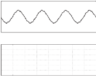
0). The output current
i
a
, reference
current
i
ref
and the corresponding current tracking error
e
i
in the steady state are shown in the
right column of Figure 17.3. Again, the tracking performance of the controller was satisfactory
and remained more or less unchanged with comparison to the previous experiment. The current
THD increased because the total amount of the current injected into the grid was reduced.
=
5
5
i
ref
i
a
i
ref
i
a
2.5
2.5
0
0
−2.5
−2.5
−5
−5
1.5
1.5
e
i
e
i
1
1
0.5
0.5
0
0
−0.5
−0.5
−1
−1
−1.5
−1.5
0
0.01
0.02
0.03
0.04
0.05
0.06
0.07
0.08
0
0.01
0.02
0.03
0.04
0.05
0.06
0.07
0.08
Time [s]
Time [s]
(a) Grid output current
, its reference
and current tracking error
5
5
THD of i
a
=3.65%
THD of i
a
=5.8%
4
4
3
3
2
2
1
1
0
0
0
5
10
15
20
25
30
0
5
10
15
20
25
30
Harmonics order
Harmonics order
(b) Spectra of the grid output current
Figure 17.3
Experimental results for a DB controller without a local load (left column) and with a
resistive local load (right column)


Search WWH ::

Custom Search