Environmental Engineering Reference
In-Depth Information
voltage quality of parallel-operated inverters, a strategy that combines the strategy in Chapter
8 with the robust droop control in Chapter 19 is presented in Chapter 20, and a strategy to
inject the right amount of harmonic voltages into the reference voltage is presented in Chapter
21, respectively.
Part IV is devoted to the synchronisation of inverters with another source. The conventional
synchronisation techniques are presented in Chapter 22, with detailed discussions about basic
PLL, STA and SOGI-PLL. In Chapter 23, a synchronisation strategy based on the operation
principles of synchronous generators is presented to quickly detect the amplitude, frequency
and phase of the fundamental component of a periodic signal.
Most of the strategies are demonstrated with extensive experimental results and, hence, can
be directly applied in practice with minimum effort.
1.2 Basics of Power Processing
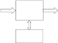
Power processing is to convert a power source into a voltage or current supply that is suitable
for the load, as shown in Figure 1.2. It involves the integration of power electronic devices and
a controller. There are four types of power processing: AC-DC conversion, DC-DC conversion,
DC-AC conversion and AC-AC conversion. These are the subject of many topics on power
electronics (Bose 2001; Erickson and Maksimovic 2001; Fisher 1991; Mohan 2003; Rashid
1993; Thorborg 1988; Vithayathil 1995), and will be briefly described here, assuming that all
the devices are ideal.
1.2.1 AC-DC Conversion
The conversion from AC to DC is often called rectification and the converter used is called a
rectifier. For an ideal rectifier, it is expected that the output voltage is a pure DC signal without
any ripples and the input current is in phase with the voltage and does not have harmonics.
According to the power electronic devices adopted, rectifiers can be divided into uncontrolled
rectifiers with diodes, phase-controlled rectifiers with thyristors and PWM-controlled rectifiers
with IGBTs or MOSFETs.
1.2.1.1 Uncontrolled Rectifiers
Figure 1.3(a) shows the simplest rectifier, which consists of a diode. For the sinusoidal input
voltage shown in Figure 1.3(b), the output voltage is shown in Figure 1.3(c). Only the positive
Power
Electronic
Devices
Power
In
Power
Out
Controller
Figure 1.2
Sketch of power processing
Search WWH ::

Custom Search