Environmental Engineering Reference
In-Depth Information
13.4.1.2 When the Neutral Current is Distorted
In this experiment, a single-phase uncontrolled rectifier loaded with an LC filter
L
=
150
μ
H
,
C
was connected to Phase S of the three-phase inverter.
Experiments were carried out with the controllers
C
1
,
C
3
,
C
5
and
C
7
designed above. The
results are shown in Figure 13.10. In all cases, there was no visible fundamental component
in
V
a
v
e
. When controller
C
1
was adopted, there was visible 3rd harmonics in
V
a
v
e
. This was
improved when controller
C
3
was adopted. However, after the 3rd harmonics was removed,
there was visible 5th harmonics in
V
a
v
e
. When controller
C
5
was adopted, the 5th harmon-
ics was removed from
V
a
v
e
; when controller
C
7
was adopted, the performance was further
improved. This clearly shows that when the number of harmonics compensated for is increased,
=
1000
μ
F
and a resistor
R
=
20
4
2
i
C
i
L
i
N
V
ave
2
1
0
0
−2
−1
−4
−2
0
0.01
0.02
0.03
0.04
0.05
0.06
0
0.01
0.02
0.03
0.04
0.05
0.06
Time [s]
Time [s]
(a) With controller
4
2
i
C
i
L
i
N
V
ave
2
1
0
0
−2
−1
−4
−2
0
0.01
0.02
0.03
0.04
0.05
0.06
0
0.01
0.02
0.03
0.04
0.05
0.06
Time [s]
Time [s]
(b) With controller
4
2
i
C
i
L
i
N
V
ave
2
1
0
0
−2
−1
−4
−2
0
0.01
0.02
0.03
0.04
0.05
0.06
0
0.01
0.02
0.03
0.04
0.05
0.06
Time [s]
Time [s]
(c) With controller
4
2
i
C
i
L
i
N
V
ave
2
1
0
0
−2
−1
−4
−2
0
0.01
0.02
0.03
0.04
0.05
0.06
0
0.01
0.02
0.03
0.04
0.05
0.06
Time [s]
Time [s]
(d) With controller
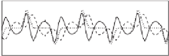
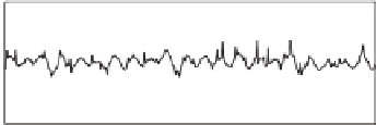
Figure 13.10
Steady-state responses when an unbalanced non-linear load was connected to the three-
phase inverter: the neutral current
i
N
, the capacitor current
i
C
and the inductor current
i
L
(left column)
and the neutral point shift
V
a
v
e
(right column)


Search WWH ::

Custom Search