Environmental Engineering Reference
In-Depth Information
40
K (H
∞
design)
K
r
(reduced)
30
20
10
K
v
0
−10
K
i
−20
−30
10
−1
10
0
10
1
10
2
10
3
10
4
10
5
10
6
10
7
10
8
10
9
Frequency (rad/sec)
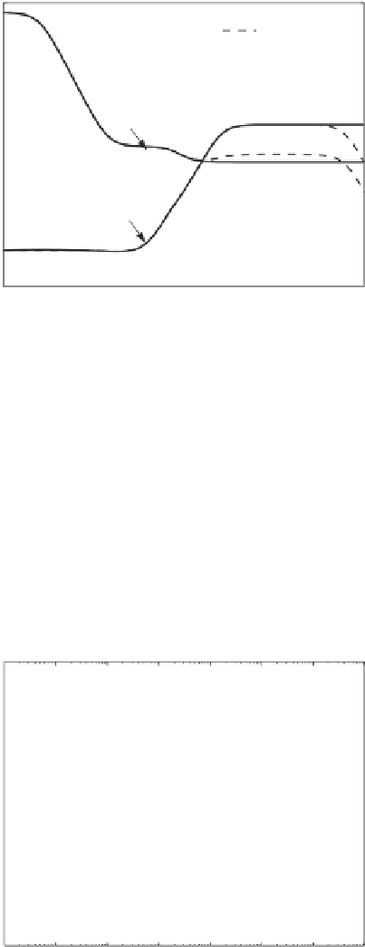
Figure 12.6
Bode plots of the controllers
K
and
K
r
12.5 Simulation Results
A single-phase converter leg was used to create a current
i
N
flowing back through the neutral
line. The phase leg had a load composed of a resistor
R
=
5 mH and it generated a sinusoidal neutral current of about 68 A peak at 50 Hz. The reduced
controller
K
r
was used in the simulation. A variable voltage component of 100 sin 200
=
5
in series with an inductor
L
π
t
V
and a resistor of 0
were put in series with the DC source of 850 V to make it more realistic.
The simulation results are shown in Figure 12.8.
.
5
40
K (H
∞
design)
K
r
(reduced)
20
0
−20
to u
N
−40
−60
to V
ave
−80
−100
−120
10
−1
10
0
10
1
10
2
10
3
10
4
10
5
10
6
Frequency (rad/sec)
Figure 12.7
Bode plots of the closed-loop transfer functions from
i
N
to
V
a
v
e
and to
u
N
with the
controllers
K
and
K
r


Search WWH ::

Custom Search