Environmental Engineering Reference
In-Depth Information
V
0
i
N
+
1
+
1
V
ave
V
u
N
i
L
i
c
V
c
p
+
DC
sL
+
R
(
C
+
+
C
)
s
-
2
+
N
N
−
+
N
N
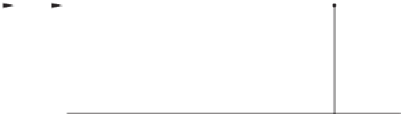
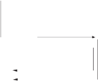
Figure 12.3
Block diagram of the uncontrolled neutral leg
12.2 Controller Design
The control objective for the plant shown in Figure 12.3 is to maintain a stable and balanced
neutral point, i.e. to make
V
a
v
e
as small as possible while maintaining the stability of the
system. The disturbances are the neutral current
i
N
and the equivalent external disturbance
V
0
defined in (12.5). Since the current
i
c
contains ripples (at the switching frequency), it must be
sensed through a low-pass filter
F
(
s
), as shown in Figure 12.4. The remaining ripples after
this filter can be interpreted as a measurement noise
n
and the measured signal
V
i
=
n
is available for feedback. Another signal available for feedback is the average voltage
V
a
v
e
.In
other words, the measured signal is
y
Fi
c
+
=
V
a
v
e
V
i
T
.
From the
H
∞
control point of view, the simplest formulation of the problem would be to
minimise the
H
∞
-norm of the transfer function from
i
N
V
0
n
T
to the average voltage
V
a
v
e
.
Such a formulation would be unrealistic, since it would ignore the fact that the disturbances
are expected in a certain frequency range and that the signal
u
N
should not be too large
(because for obvious physical reasons,
V
−
<
V
+
). Thus, as is usual in applications of
the
H
∞
control theory, the weighting functions
W
v
and
W
u
are introduced to
V
a
v
e
and
u
N
,
u
N
<
i
N
I
0
w
ρ
I
n
n
ζ
V
0
i
N
+
1
u
N
1
i
L
-
+
i
c
V
c
V
av
e
V
u=p
V
v
+
W
v
(
s
)
DC
sL
+
R
(
C
+
+
C
)
s
2
+
N
N
−
+
N
N
z
V
u
W
u
(
s
)
+
F
(
s
)
+
(
s
)
V
ave
(
s
)
y
V
i
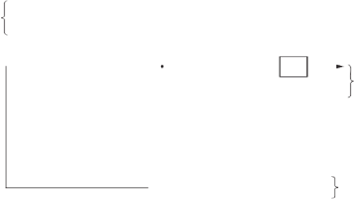
Figure 12.4
Formulation of the
H
∞
control problem


Search WWH ::

Custom Search