Environmental Engineering Reference
In-Depth Information
0.1
100
0.05
50
0
0
−0.05
−50
−0.1
−100
0
0.02
0.04
0.06
0.08
0.1
0.08
0.085
0.09
0.095
0.1
Time [s]
Time [s]
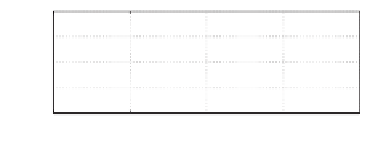
(a) Shift of the neutral point
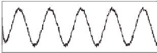
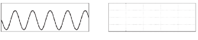
(b) Filtered inductor voltage
2
0.4
i
N
i
L
1
0.2
0
0
−1
−0.2
−2
−0.4
0.099
0.0992
0.0994
0.0996
0.0998
0.1
0.08
0.085
0.09
0.095
0.1
Time [s]
Time [s]
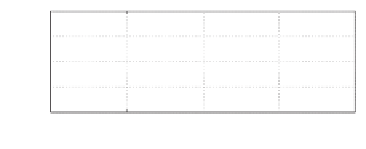
(c) Inductor
and neutral
currents
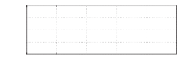
(d) Filtered capacitor current
Figure 11.9
Simulation results when
i
N
=
0
0 V although there are some pulses left after filtered by the hold filter; the current flowing
through the inductor is nearly a triangle wave with an amplitude of about 1
25 A; the current
i
c
is very small although there are some spikes, which are not shown in the figure because of
the filtering effect of the hold filter
F
(
s
). The average of the inductor current is 0, which is the
same as the neutral current.
.
11.5.2 With a 50 Hz Neutral Current
When the buck converter has a single-phase load
R
5mH
and works at 50 Hz, the peak amplitude of the output voltage is about 360 V. This offers a
neutral current of about 68 A peak. The simulation results are shown in Figure 11.10. The
=
5
in series with an inductor
L
=
0.1
300
0.05
150
0
0
−0.05
−150
−0.1
−300
0
0.02
0.04
0.06
0.08
0.1
0
0.02
0.04
0.06
0.08
0.1
Time [s]
Time [s]
(a) Shift of the neutral point
(b) Filtered inductor voltage
120
0.5
i
N
i
L
80
0.25
40
0
0
−0.25
−40
−80
−0.5
0
0.02
0.04
0.06
0.08
0.1
0
0.02
0.04
0.06
0.08
0.1
Time [s]
Time [s]
(c) Inductor
and neutral
currents
(d) Filtered capacitor current
Figure 11.10
Simulation results when the main component of the neutral current is 68 A, 50 Hz


Search WWH ::

Custom Search