Environmental Engineering Reference
In-Depth Information
V
+
R
C
~
R
S
i
N
V
DC
~
T
~
R
C
V
-
neutral
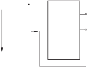
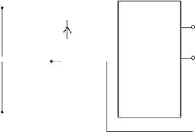
(a) Split DC link
V
+
R
~
S
+
S
C
V
DC
~
L
N
S
-
T
~
i
N
V
-
neutral
(b) Neutral leg as used with three-dimensional space vector modulation
Figure 10.2
Conventional topologies to generate a neutral line
particular, when the neutral current has a DC component. In order to improve the performance
of the split DC link, different neutral point balancing strategies are reported, usually using
redundant states of the Space Vector Pulse Width Modulation (SVPWM) (Bendre
et al.
2006;
Salaet
et al.
2006; Zhou and Rouaud 2001) or varied voltage-balancing modulation techniques
(Busquets-Monge
et al.
2008a; Dai
et al.
2008b; Ghennam
et al.
2010; Lewicki
et al.
2011;
Wang and Li 2010; Zaragoza
et al.
2009). However, this means the control of the neutral point
is not decoupled from the control of the inverter, which may cause problems as well. Hence,
this topology is not suitable for DC-AC converters which supply power to possibly unbalanced
loads or to the grid.
10.3 Conventional Neutral Leg
A better way to provide a neutral line is to add an additional fourth leg, called a neutral leg,
to the conventional three-leg converter (Jahns
et al.
1993), as shown in Figure 10.2(b). It can


Search WWH ::

Custom Search