Environmental Engineering Reference
In-Depth Information
100
15
i
A
i
B
i
C
10
50
5
0
0
−5
−50
−10
−100
−15
0
0.04
0.08
0.12
0.16
0.2
0
0.04
0.08
0.12
0.16
0.2
Time/s
Time/s
(a) Load current
(b) Grid-side currents
5.8
2000
i
sa
i
sb
i
sc
5.4
1000
5
0
4.6
−1000
4.2
−2000
0
0.04
0.08
0.12
0.16
0.2
0
0.04
0.08
0.12
0.16
0.2
Time/s
Time/s
(c) DC-bus voltage
(d) Compensation currents
100
10
8
75
6
50
4
25
2
0
0
0
0.04
0.08
0.12
0.16
0.2
0.12
0.14
0.16
0.18
0.2
Time/s
Time/s
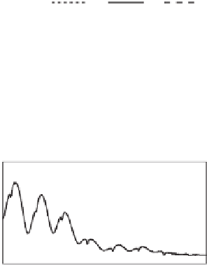
(f) THD of Phase-A grid-side current (0.12~0.2 s)
(e) THD of Phase-A grid-side current
Figure 9.7
Effect of the compensation strategy when cos
θ
=
1
9.6 Summary
A topology incorporating a three-phase V/V transformer and a three-phase converter is pre-
sented for traction power systems. It provides a single feeding wire instead of two phase
feeding wires. The converter is operated as a static power conditioner with a multi-functional
control strategy so that it is able to balance the grid currents, to compensate for reactive power
and to suppress current harmonics caused by locomotives. As a result, the power quality issues
often seen in traction power systems, such as negative-sequence currents, harmonics and low
power factor, are all dealt with. Compared to the traditional two-phase traction systems, this
system has a simple structure and reduced neutral sections, which enhances system reliability.
The strategy is validated with simulation results.


Search WWH ::

Custom Search