Environmental Engineering Reference
In-Depth Information
A
B
C
i
B
i
C
i
A
B
A
C
a
i
a
i
b
b
c
i
c
i
rb
i
ra
i
sc
i
sb
i
sa
i
L
i
L
Section
insulator
SPC
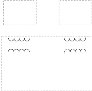
Figure 9.1
Traction power system with a single feeding wire equipped with a V/V transformer
The load current
i
L
is assumed to be purely sinusoidal without any harmonics for the
moment (the case with harmonic currents will be discussed later) and the power factor is cos
θ
.
Then, the load current can be expressed as
6
−
θ
I
L
=
I
L
1
∠
(9.2)
where
I
L
1
is the RMS value of the fundamental load current. The three-phase grid currents
without any compensation are
⎧
⎨
6
−
θ
I
L
1
K
V
∠
I
A
=
,
I
L
1
K
V
∠
5
6
π
−
θ
(9.3)
I
B
=
−
,
⎩
I
C
=
0
,
as shown in Figure 9.2(a). It is obvious that the three-phase grid currents are unbalanced. Both
reactive and active current components are included in
I
A
and
I
B
as they are not in phase
with
U
A
and
U
B
, respectively. Phase-A current leads its voltage by
6
−
θ
and Phase-B current
−
6
leads its voltage by
−
θ
. A significant amount of negative-sequence currents exists in the
grid currents.


Search WWH ::

Custom Search