Environmental Engineering Reference
In-Depth Information
K
(
s
)
i
=
i
+
R
v
L
o
K
i
K
i
-
u
v
r
K
R
(
s
)+1
(a) Equivalent block diagram
V
DC
-
+
u
f
i
L
i
i
o
v
o
L
CB
u
K
Admittance
of resonant
filters
IGBT
H-bridge
PWM
R
C
AC bus
K
i
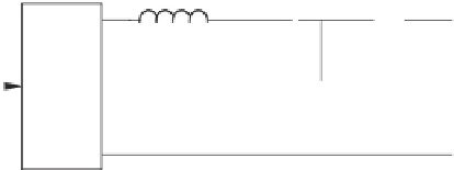
(b) Equivalent physical circuit
Figure 8.4
Equivalent structures of the controller shown in Figure 8.2
C
. In other words, the inner-loop controller shown in Figure 8.2 is equivalent to adding the
admittance block
K
R
(
s
)
K
i
to parallel with the filter
C
.
The admittance block
K
R
(
s
)
K
i
with the
K
R
(
s
) given in (8.3) is
K
R
(
s
)
K
i
2
ξ
h
ω
s
K
h
K
i
,
=
)
2
×
s
2
+
2
ξ
h
ω
s
+
(
h
ω
h
=
3
,
5
,...
which is the parallel connection of the admittance branches of
2
ξ
h
ω
s
K
h
K
i
=
1
)
2
×
K
i
K
i
K
h
+
K
i
K
h
h
ω
s
2
+
2
ξ
h
ω
s
+
(
h
ω
K
h
s
+
2
ξ
h
ω
2
ξ
s
K
i
for
h
=
3
,
5
,...
. Each branch is equivalent to the series connection of resistance
K
h
, induc-
K
i
2
ξ
h
ω
K
h
2
ξ
K
h
tance
. Hence,
the controller shown in Figure 8.2 is equivalent to adding shunt series resonant filters at
individual harmonic frequencies to the output to bypass harmonic current components. It is
interesting to see that
K
i
and capacitance
h
ω
K
i
, which resonate at the
h
-th harmonic frequency
h
ω
K
h
is the remaining impedance at the
h
-th harmonic frequency. In order
to completely eliminate the
h
-th harmonic voltage component,
K
i
should be zero because
K
h
is finite. This indicates that forcing the output impedance of the inverter resistive via the cur-
rent feedback increases certain harmonic voltage components. However, it is able to dampen
high frequency oscillations (Dahono
et al.
2001; Li 2009), which may reduce some harmonic
voltage components. Hence, there exists a trade-off when determining
K
i
.


Search WWH ::

Custom Search