Environmental Engineering Reference
In-Depth Information
V
DC
-
+
u
f
i
o
i
v
o
L
CB
u
IGBT
H-bridge
PWM
C
AC bus
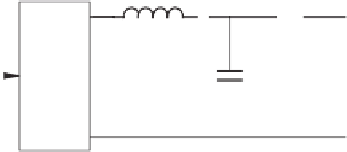
Figure 8.1
Single-phase inverter with a PWM block and an LC filter
Since the average of
u
f
over a switching period is the same as
u
, there is approximately
v
r
−
K
i
i
+
K
R
(
s
)(
v
r
−
v
o
)
=
sLi
+
v
o
,
which gives
v
o
=
v
r
−
·
,
Z
o
(
s
)
i
(8.1)
where the output impedance
Z
o
(
s
)is
sL
+
K
i
Z
o
(
s
)
=
K
R
(
s
)
.
(8.2)
1
+
The resistive and inductive part of the output impedance are all decreased when the real part
of
K
R
is positive, which is able to improve the THD of the output voltage. In general, there
are harmonics in the current
i
because of non-linear loads and/or the pulse width modulation,
which cause harmonic voltage drops on the output impedance
Z
o
. Since the reference
v
r
is
often purely sinusoidal and does not contain any harmonic voltage components, the harmonic
voltage drop on the output impedance
Z
o
appears in the output voltage, which degrades the
voltage quality and causes a high THD. It is hence worth noting that the main factor that
affects the voltage THD is the value of the output impedance instead of the type (resistive or
inductive). The THD can be small even if the output impedance is inductive as long as it is
small. The output impedance does not have to be resistive and the voltage THD can be large
if the output impedance is resistive and large. Another observation is that the inductor current
feedback increases the output impedance, which increases the voltage THD, and the voltage
feedback decreases the output impedance, which decreases the voltage THD.
v
o
i
-
K
i
K
R
(
s
)
-
u
v
r
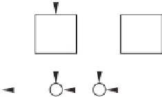
Figure 8.2
Controller to improve voltage THD


Search WWH ::

Custom Search