Environmental Engineering Reference
In-Depth Information
24
30
v
o
i
20
22
10
20
0
18
−10
−20
16
0.9
0.91
0.92
0.93
0.94
0.95
0.96
0.9
0.91
0.92
0.93
0.94
0.95
0.96
Time [s]
Time [s]
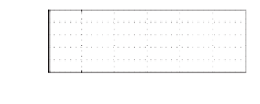
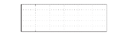
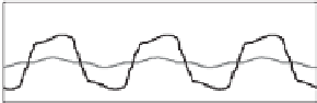
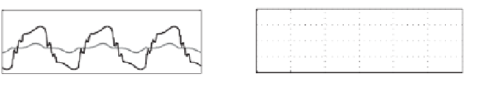
(a) C-inverter with
C
o
= 479
μ
F
24
30
v
o
i
20
22
10
20
0
18
−10
16
−20
0.9
0.91
0.92
0.93
0.94
0.95
0.96
0.9
0.91
0.92
0.93
0.94
0.95
0.96
Time [s]
Time [s]
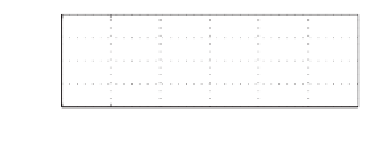
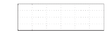
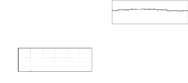
(b) C-inverter with
C
o
= 325
μ
F
24
30
v
o
i
20
22
10
20
0
18
−10
16
−20
0.9
0.91
0.92
0.93
0.94
0.95
0.96
0.9
0.91
0.92
0.93
0.94
0.95
0.96
Time [s]
Time [s]
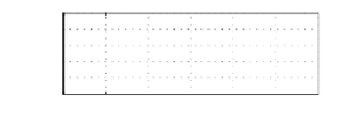
(c) R-inverter with
K
i
=4
24
30
v
o
i
20
22
10
20
0
18
−10
16
−20
0.9
0.91
0.92
0.93
0.94
0.95
0.96
0.9
0.91
0.92
0.93
0.94
0.95
0.96
Time [s]
Time [s]
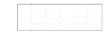
(d) L-inverter
Figure 7.9
Experimental results for the case with
L
=
2
.
35 mH: output voltage and current (left
column) and THD of the output voltage (right column)
7.6.2 The Case with L
25
mH
The experimental results when the inverter was designed to have different types of output
impedance is shown in Figure 7.10. When the inverter was designed to have a capacitive
output impedance to minimise the effect of both 3rd and 5th harmonics, the THDwas improved
by 2% from the case with an inductive output impedance and by nearly 4% from the case
with a resistive output impedance (with
K
i
=
=
0
.
4). When the inverter was designed to have
a capacitive output impedance to minimise the effect of the 3rd harmonics, the THD was
improved by about 3% and 1%, respectively. It is worth noting that when the inverter was
designed to have a capacitive output impedance, the THD of the output voltage dropped
below 5%.
0
.


Search WWH ::

Custom Search