Environmental Engineering Reference
In-Depth Information
7.4.4 Special Case III: to Minimise the 5th Harmonic Component
In this case, the optimal
C
o
is
1
C
o
=
(5
ω
∗
)
2
L
and the corresponding impedance is
ω
∗
L
ω
ω
∗
ω
25
ω
=
ω
∗
−
.
Z
o
(
j
)
j
The gain factor
ω
∗
−
25
ω
∗
ω
of the imaginary part with respect to the normalised frequency
ω
∗
is
ω
=
ω
∗
. At the fundamental
also shown in Figure 7.5. It changes from negative to positive at
5
ω
=
ω
∗
, the output impedance is
frequency, i.e., when
ω
∗
L
ω
∗
L
Z
o
=−
j
24
≈−
j
24
.
This is capacitive as well.
7.5 Simulation Results for R-, L- and C-inverters
Simulations were carried out on a single-phase inverter powered by a 42 V DC voltage
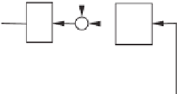
supply. The inverter was equipped with an outer-loop controller, as shown in Figure 7.6, to
regulate the output voltage. This outer-loop controller is actually the robust droop controller
(Zhong 2012c) for C-inverters to be discussed in detail in Chapter 19. The parameters were
n
i
=
5 kHz and the frequency
of the system was 50 Hz. The rated voltage was 12 V. The filter capacitance was 22
2
.
2,
m
i
=
0
.
14 and
K
e
=
20. The switching frequency was 7
.
μ
F
E
*
-
K
RMS
e
+
E
i
1
P
i
n
i
s
v
o
v
ri
+
1
i
m
i
s
Q
i
ω
i
t+
δ
i
*
ω
Figure 7.6
Outer-loop controller to generate the voltage reference
v
r
for C-inverters. See Chapter 19
for more details


Search WWH ::

Custom Search