Environmental Engineering Reference
In-Depth Information
i
1
sC
o
-
u
v
r
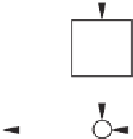
Figure 7.4
Controller to achieve a capacitive output impedance
Since the average of
u
f
over a switching period is the same as
u
, there is approximately
1
sC
o
i
v
r
−
=
+
v
o
,
sLi
which leads to
v
o
=
v
r
−
Z
o
(
s
)
·
i
,
with the output impedance
Z
o
(
s
) of the inverter given as
1
sC
o
.
Z
o
(
s
)
=
sL
+
(7.3)
If the capacitor
C
o
is chosen small enough, the effect of the inductor is not significant and
the output impedance can be made nearly purely capacitive at the fundamental frequency, i.e.,
roughly
1
sC
o
.
Z
o
(
s
)
≈
Such inverters are called C-inverters.
7.4 Design of C-inverters to Improve the Voltage THD
As discussed in Section 2.1.2, the THD of the output voltage depends on the output impedance
at the harmonic frequencies. If the output impedance of an inverter is designed to be capacitive,
then it is possible to improve the THD of the output voltage by selecting appropriate
C
o
.
7.4.1 General Case
According to (7.3), there is
h
2
Z
o
(
jh
ω
∗
)
1
2
ω
∗
L
=
−
,
ω
∗
C
o
h


Search WWH ::

Custom Search