Environmental Engineering Reference
In-Depth Information
4
30
i
ref
i
a
u
ref
u
A
2
15
0
0
−2
−15
−4
−30
4
4
e
i
e
u
2
2
0
0
−2
−2
−4
−4
1.7
1.8
1.9
2
2.1
2.2
1.7
1.8
1.9
2
2.1
2.2
Time [s]
Time [s]
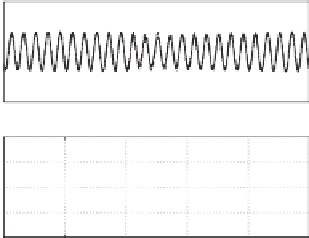
(a)
i
a
, its reference
i
ref
and the error
e
i
(b)
u
A
, its reference
u
ref
and the error
e
u
Figure 6.17
Detailed responses when the local load was changed from 12
to 100
at
t
=
1
.
88 s
Figure 6.17 for the change from 12
to 100
at
t
=
1
.
88 s and in Figure 6.18 for the change
from 100
61 s. The current controller took about 5 cycles to settle down,
which is in line with the findings from the previous experiment. There was no noticeable
change in the inverter local load voltage.
to 12
at
t
=
6
.
6.6.4 Seamless Transfer of the Operation Mode
The transient response of the grid current when the inverter was changed from the stand-alone
mode to the grid-connected mode and back is shown in Figure 6.19. The detailed responses
during the transfers are shown in Figures 6.20, 6.21 and 6.22.
At
t
1 s, the inverter was connected to the grid. The details of the transfer from the
stand-alone mode to the grid-connected mode are shown in Figure 6.20. There was not much
=
4
30
i
ref
i
a
u
ref
u
A
2
15
0
0
−2
−15
−4
−30
2
4
e
i
e
u
1
2
0
0
−1
−2
−2
−4
6.4
6.5
6.6
6.7
6.8
6.9
6.4
6.5
6.6
6.7
6.8
6.9
Time [s]
Time [s]
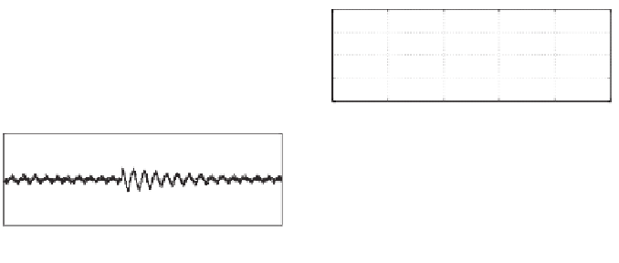
(a)
i
a
, its reference
i
ref
and the error
e
i
(b)
u
A
, its reference
u
ref
and the error
e
u
Figure 6.18
Detailed responses when the local load was changed from 100
to 12
at
t
=
6
.
61 s


Search WWH ::

Custom Search