Environmental Engineering Reference
In-Depth Information
Local
load
V
DC
-
+
S
c
u
f
u
o
Inverter
bridge
PWM
u
g
L
f
u
u
i
1
i
c
i
2
L
g
R
f
R
g
C
f
filter inductor
grid interface inductor
u
c
grid
R
d
neutral
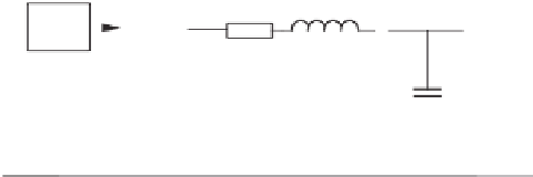
Figure 6.1
Sketch of a grid-connected single-phase inverter with local loads
load voltage. An inner current loop can still be added to the presented structure inside the
voltage loop without any difficulty to perform the conventional function, if needed. The
H
∞
repetitive control strategy (Hornik and Zhong 2009, 2010b, 2011) is adopted here to design
the controllers but this is not a must and other approaches can be used as well.
The multiloop control strategies analysed in (Loh and Holmes 2005) indicated that it was
impossible to stabilise an inverter with a proportional feedback of the capacitor voltage and
that the performance with an inner-loop proportional-derivative voltage controller is not good
either. It is demonstrated in this chapter that excellent performance can be achieved with an
inner-loop repetitive controller.
6.2 Control Scheme
Figure 6.1 depicts the structure of a single-phase inverter connected to the grid. It consists of
an inverter bridge, an LC filter and a grid interface inductor connected with a circuit breaker.
It is worth noting that the local loads are connected in parallel with the filter capacitor. The
current
i
1
flowing through the filter inductor is called the filter inductor current and the current
i
2
flowing through the grid interface inductor is called the grid current. The control objective
is to maintain low THD for the inverter local load voltage
u
o
and, simultaneously, for the grid
current
i
2
.
As a matter of fact, the system can be regarded as two parts, as shown in Figures 6.2 and 6.3,
cascaded together. Hence, a cascaded controller, as shown in Figure 6.4, can be adopted and
designed naturally. It consists of two loops: an inner voltage loop to regulate the inverter local
load voltage
u
o
and an outer current loop to regulate the grid current
i
2
. According to the basic
principles of control theory of cascaded control, if the dynamics of the outer loop is designed
to be slower than that of the inner loop, then the two loops can be designed separately. As a
result, the outer-loop controller can be designed under the assumption that the inner-loop is
already in the steady state, that is,
u
o
=
u
ref
. It is also worth stressing that the current controller
is in the outer loop and the voltage controller is in the inner loop. This is contrary to what is
normally done. In this chapter, both controllers are designed using the
H
∞
repetitive control
strategy because of its excellent performance in reducing THD.
The main functions of the voltage controller are: to deal with power quality issues of the
inverter local load voltage even under unbalanced and/or non-linear local loads, to generate


Search WWH ::

Custom Search