Biomedical Engineering Reference
In-Depth Information
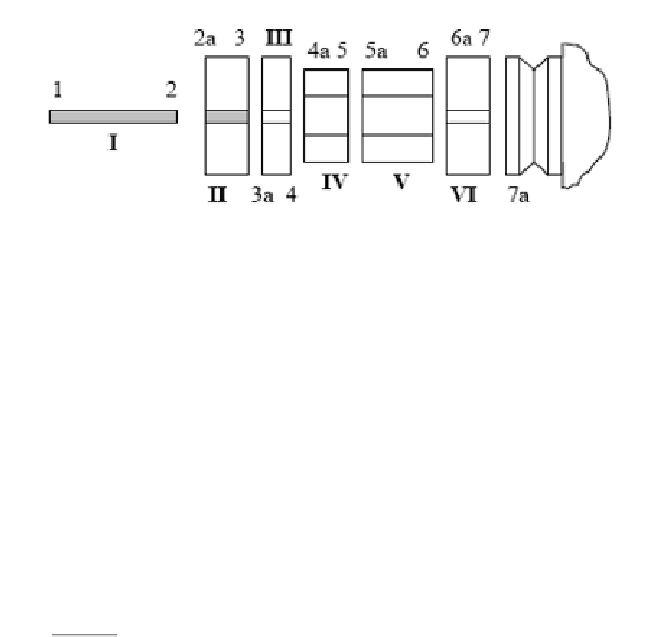
Figure 9. Model of the tool (I), collet holder (II-VI) and spindle (flange shown at
coordinate 7a) [41].
The spindle holder base receptances have been determined by defining the
receptance for the standard tool holder:
HH
55
55
a
L
55
()
S
where, H
55
is the direct FRF at coordinate 5, H
55a
is the cross FRF at
coordinate 5 and S was considered to be 50.5mm.
The rotation to moment receptance was determined as:
2
L
N
L
55
55
55
P
55
H
H
55
55
where H
55
was measured and N
55
was assumed equal to L
55
by reciprocity.
An assembly receptance matrix has been defined as:
H
L
55
55
G
()
55
N
P
55
55
Further, Timoshenko beam models were used for substructures I and II,
and the tool and tool holder have been rigidly coupled using:
1
RS
R
R
R
R
R
55
55
56
66
6
aa
6
65
1
RS
R
R
R
R
R
77
77
76
a
66
6
a
6
a
6
a
7
1
RS
R
R
R
R
57
56
66
6
a
6
a
6
a
7
1
RS
R
R
R
R
75
76
a
66
6
a
6
a
65