Biomedical Engineering Reference
In-Depth Information
A housing was used to position the lasers directly across from the
photodiodes. As particle crosses a laser beam, the interruption of the laser
beam to the photodiode is detected. The change in light intensity in the
photodiode is recorded as a change in voltage, and this is recorded by a digital
oscilloscope. Since the position of the second laser and photodiode is at a
known distance from the first, speed is calculated by utilizing the digital
oscilloscope to measure the time difference between abrupt voltage changes.
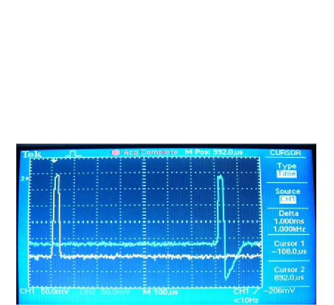
Figure 41 shows the results of a test. The two voltage spikes from each sensor
can be clearly seen, and the trace function is used from the oscilloscope to
directly measure the time interval between the two voltage spikes.
Reproduced with permission. Copyright retained by Inderscience Publishers.
Figure 41. Typical Digital Oscilloscope Output from Velocity Measurement Device.
The housing was for the photodiodes and lasers was developed and
manufactured as part of this study. Material for this housing is 6061-T6 and
was chosen due to its availability and ease of manufacturing. The housing
consists of separate blocks and was designed to be modular. Before
manufacturing the components, individual parts were designed and assembled
in Pro/Engineer to ensure correct fits. This allows the user to use up to three
position references and vary the distance between the measurement points.
The housing assembly is then mounted to the end of the barrel. The housing is
pictured in Figure 42 and Figure 43. To be effective for this study, the
measurement system must prove to be sufficiently precise. This will become
critical in future applications to determine the critical velocity of particle and
substrate combinations (Raletz, Vardelle, and Ezo'o, 2006).