Biomedical Engineering Reference
In-Depth Information
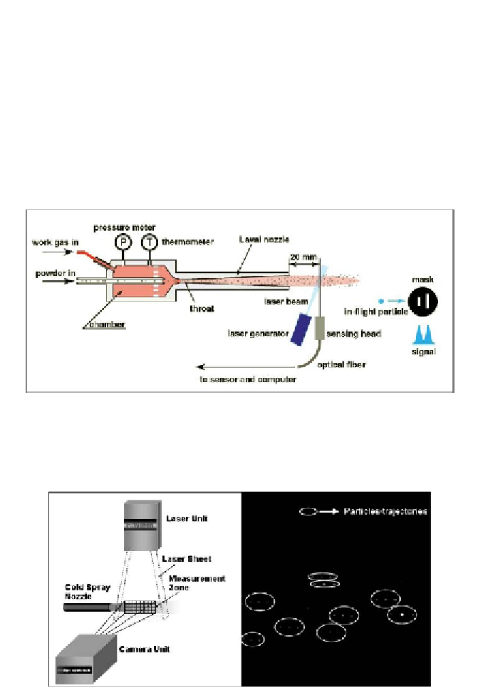
the time interval between the two slits (Fukunama et al., 2006). The distance
between the two slits is predetermined and known, allowing for a
straightforward calculation of velocity. A schematic of this method is shown
below in Figure 10. Raletz et al. (1998) use an alternative method, employing
an imaging technique. In this method a CCD camera sensor with a fast shutter
opens for 100 µs, and the particle spray jet is illuminated by three consecutive
laser pulses. The image is captured, and the velocity is then determined by
knowing the interval between pulses and the distance, which is determined by
an image processing algorithm (Raletz et al., 1998). Figure 11 illustrates the
technique.
Reproduced with permission. Copyright retained by Inderscience Publishers.
Figure 10. Schematic of system to measure velocity in cold spray particles (Fukunama
et al., 2006).
Reproduced with permission. Copyright retained by Inderscience Publishers.
Figure 11. Illustration of imaging technique employed by Raletz et al. (1998).