Biomedical Engineering Reference
In-Depth Information
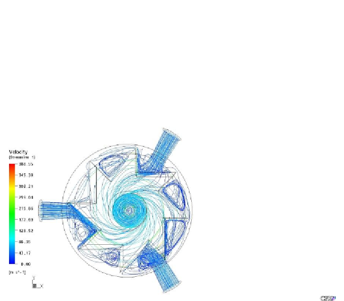
Flow topology: Figure 4 shows the flow pattern in rotor with 90-degree
blade angle. Air enters into the housing from three inlets with a pressure of 60
psi and exists from outlet at a pressure of zero. The three inlets are normal to
the surface of the housing and the outlet is at the center of the housing. Air
entering from the inlets impinges on the rotor surfaces and flows inside of
housing. At the hollow part of the rotor, the fluid is swirled and at the outlet
the velocity increases due to the sudden contraction of the surface area at the
outlet.
Copyright retained by Inderscience Publishers.
Figure 4. Streamlines describing the flow pattern for rotor with 90-degree blade angle
at one million rpm rotational speed of rotor. Reproduced with permission.
Pressure Variation: Figure 5 describes the pressure variation on the
surfaces of the rotor. From the figure it can be observed that the regions of the
rotor, where the fluid impinges directly are having maximum pressure due to
the stagnation of the fluid compared to the other regions of the rotor. At the
stagnation point the total kinetic energy of the fluid is converted into pressure
energy, so the maximum pressure occurs at the stagnation point of the fluid.
The pressure coefficient on the rotor can be determined from the Eq. 9 by
substituting values of maximum pressure and minimum pressure on the rotor
as shown in Figure 5 and inlet pressure (60 Psi).