Biomedical Engineering Reference
In-Depth Information
lamellar spacing on each chip was determined. Transient chip curl was
measured at the first 90
o
of tight chip curl. The curl radii was then compared
with the calculated value derived using the idealized model, taking into
account the degree of bending of the cutting tool.
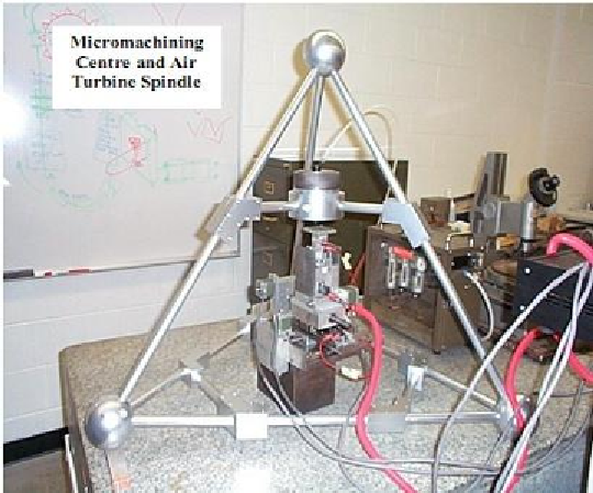
Figure 2. Micromachining centre equipped with a high-speed air turbine spindle for
rotating coated micro milling tools. Reproduced with permission. Copyright retained
by Inderscience Publishers.
Table 1. Experimental data comparing initial chip curl during
micromachining and initial chip curl predicted by the model. The depth of
cut was 100
m. Note that variable primary shear plane is observed
during the experiments. Reproduced with permission. Copyright retained
by Inderscience Publishers
Rake angle
after bending
(
O
)
Shear plane
angle
(
O
)
Mean lamellar
spacing (μm)
Observed chip
curl (mm)
Calculated chip
curl (mm)
22
37
0.98
17.55
18.01
15
25
1.55
14.42
14.65
8
18
1.9
16.55
17.1
3
12
2.95
15.82
16.22