Environmental Engineering Reference
In-Depth Information
Standstill
Standstill
Start
Start
Wind speed
Below the rated
wind speed
Wind speed
Below the rated
wind speed
Above the rated
wind speed
Above the rated
wind speed
Vane position
(
F
L
=0)
Vane position
(
F
L
=0)
Continuous
adjustment
Continuous
adjustment
Laminar flow
(Phase II)
Laminar flow
(Phase II)
Discontinued flow
(Phase III)
Discontinued flow
(Phase III)
α
α
v
Wi
v
Wi
v
I
v
I
α
α
v
I
v
I
v
Wi
v
Wi
α
α
α
α
v
Wi
v
Wi
-v
R
-v
R
-v
R
-v
R
F
L,t
=F
L
F
L,t
=F
L
F
L,t
F
L,t
F
L,t
F
L,t
γ
γ
F
L
F
L
γ
γ
F
L,a
F
L,a
F
L,a
F
L,a
F
L
F
L
Direction of rotation
Direction of rotation
Direction of rotation
Direction of rotation
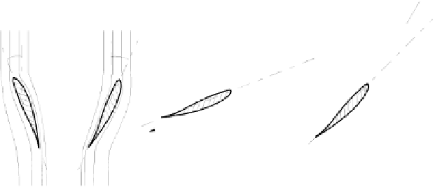
Fig. 7.21
Flow conditions at the rotor of a pitch-controlled wind energy converter (for an
explanation of symbols see text; phases refer to Fig. 7.17; see /7-5/)
For isolated grids which, unlike grid-connected operation, are not necessarily
aimed at achieving a maximum energy output, blade adjustment offers the addi-
tional ability of controlling power output by blade adjustment and of adjusting the
power yield to the current energy demand (i.e. on principle, demand-side con-
verter operation is possible).
Due to demand or grid-related reasons (for instance, in case of isolated grids
with high wind energy converter capacities) the energy fed into the grid by the
generator may be inferior to the theoretical capacity to be achieved according to
the characteristic power curve. At decreasing flow speed the capacity may be
maintained within certain limits by readjustment measures. Thus, like other types
of power-controlled power plants, wind energy converters can also be controlled
to a certain extent.
In comparison to stall control, pitch control allows for intentional and relatively
smooth shut-down of the converter upon exceeding cut out wind speed (transition
from phase III to phase IV; see Fig. 7.17). Pitch control avoids abrupt transition
from the installed capacity to zero and thus prevents the resulting high mechanical
strain exerted on the converter and on the power grid or conventional reserve ca-
pacity power stations.
7.2.5
Wind parks
Wind park design.
Wind energy converters may be installed individually in ex-
posed positions, for instance at the hilltops of low mountain ranges with free air-
flow, in rows (e.g. converters positioned along a dike) or in groups (e.g. posi-
tioned in lines, one behind the other). For the latter two variants certain minimum
distances, depending on the respective site conditions, need to be observed, to


Search WWH ::

Custom Search