Environmental Engineering Reference
In-Depth Information
exposed to moving air than on the topside (suction side) which produces a force ver-
tically to the flow angle (lifting force
F
L
). Besides the lifting force also drag force
F
D
incidents on the cross-section which is higher as in the case of symmetrical
blow (blow angle
α
> 0) (Fig. 7.4).
F
D
F
D
v
Wi
v
Wi
Cross-section profile
Cross-section profile
F
L
F
L
p
top
< p
bottom
p
top
< p
bottom
p
top
p
top
F
D
F
D
v
Wi
v
Wi
α
α
p
bottom
p
bottom
Cross-section profile
Cross-section profile
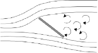
Separated turbulent flow
Separated turbulent flow
Cross-section
profile
Cross-section
profile
v
Wi
v
Wi
Fig. 7.4
Effect of the wind speed on a cross-section profile exposed to airflow
(top: orien-
tation towards flow direction; centre: orientation at a certain flow angle relative to wind
speed while laminar flow is present; bottom: orientation at a certain inflow angle
relative to
wind speed with separated turbulent flow; for an explanation of symbols see text)
The lifting force
F
L
(Equation (7.12) or Fig. 7.5), that can be sub-divided into a
tangential component in circumferential direction
F
L,t
and an axial component
F
L,a
regarding wind velocity direction and the drag force
F
D
(Equation (7.13) or
Fig. 7.5), that can also be sub-divided into a tangential
F
D,t
and an axial compo-
nent
F
D,a
are dependent on air density
ρ
Wi
, inflow velocity
v
I
and the cross-section
surface projected to the wind attack surface (in case of two-dimensional treatment
of the profile length
l
and, ideally, of an infinitely thin profile thickness
b
(Fig. 7.6, right)) as well as on the lift coefficient
c
l
and drag coefficients
c
d
.
1
2
F
=
ρ
v
l
c
(
α
)
b
(7.12)
L
Wi
I
l
2
1
2
F
=
ρ
v
l
c
(
α
)
b
(7.13)
D
Wi
I
d
2


Search WWH ::

Custom Search