Environmental Engineering Reference
In-Depth Information
The height of the air-type collector increases towards the tower. According to
this, the flow speed is not increased too much, so that friction losses are kept low.
Additionally the losses during the direction change of the air from the horizontal
into the vertical direction are minimised.
Storage.
If a less pronounced electricity generation peak is desired for the early
afternoon, while higher power generation is foreseen for the evening hours, the
solar energy can be stored intermediately. For this purpose, water-filled hoses or
cushions can be used, which, placed on the collector bottom, considerably en-
hance the already existing natural heat storage capacity of the ground.
Since already for very low water flow speeds, due to natural convection inside
the hoses, heat transfer between the hoses and the water is considerably higher
than between the radiation-absorbing surface of the earth (and the soil layers lo-
cated underneath) below the collector, and also because the heat capacity of water
is about five times higher than that of soil, the water inside the hoses stores part of
the incident solar radiation. This heat is only released during the night when air
temperatures inside the collector are below the water temperature inside the hoses.
This is why solar updraft tower power plants can be operated day and night, solely
driven by the sun.
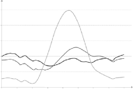
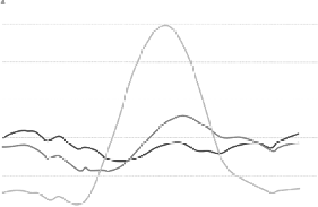
Hoses are only filled once and remain sealed afterwards so that no water is eva-
porated. Depending on the desired performance characteristic the water quantity
inside the hoses should correspond to a mean water depth below the collector of 5
to 20 cm (Fig. 5.28).
100
100
100
100
100
100
Only ground storage
Only ground storage
80
80
80
80
80
80
60
60
60
60
60
60
Water layer
10 cm
Water layer
10 cm
Water layer 20 cm
Water layer 20 cm
40
40
40
40
40
40
20
20
20
20
20
20
0
0
0
0
0
0
0:00
0:00
0:00
0:00
0:00
0:00
3
:
00
3
:
00
3
:
00
3
:
00
3
:
00
3
:
00
6:00
6:00
6:00
6:00
6:00
6:00
9:00
9:00
9:00
9:00
9:00
9:00
12:00
12:00
12:00
12:00
12:00
12:00
15:00
15:00
15:00
15:00
15:00
15:00
18:00
18:00
18:00
18:00
18:00
18:00
21:00
21:00
21:00
21:00
21:00
21:00
0:00
0:00
0:00
0:00
0:00
0:00
Tim e during the day in h
Tim e during the day in h
Fig. 5.28
Effect of heat-storing water hoses, located below the collector roof, on the chro-
nological sequence of power provision (simulation results)
Tower.
The tower or chimney represents the actual thermal engine
of a solar up-
draft tower power plant. In a first approximation, the updraft of the air heated
inside the collector is proportional to the air temperature rise obtained inside the


Search WWH ::

Custom Search