Biomedical Engineering Reference
In-Depth Information
(a)
(b)
(c)
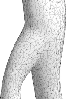
Fig. 13.5.
Remeshing of an iliac bifurcation: a) part of the initial STL triangulation, b) remeshed
geometry with the harmonic mapping using the MeshAdapt meshing algorithm, c) remeshed ge-
ometry with the presented conformal mapping using a frontal 2D meshing algorithm
described in [30] (Fig. 13.4a). Next, each mesh partition (orange and green) is
parametrized onto a surface in
2
with a specific mapping algorithm (Fig. 13.4bc).
We show two different mappings: a Laplacian harmonic map onto a unit disk
(Fig. 13.4b) and the presented conformal map with open boundaries (Fig. 13.4c).
As can be seen, the conformal mapping is much less distorted.
After the mapping has been computed, the parametrized surface is remeshed using
a 2D mesh generation algorithm and the new triangulation is then mapped back to
the original surface. Fig. 13.5 shows part of the remeshed iliac bifurcation for both
the harmonic mapping and the conformal map.
Fig. 13.6 presents the quality histogram for the surface remeshing of the iliac
artery. The presented remeshing algorithm based on finite element conformal maps
is compared with different surface remeshing techniques: two direct remeshing tech-
R
1
1
0.1
0.1
0.01
0.01
0.001
0.001
Initial STL
0.0001
0.0001
Harmonic map
Convex map
1e-05
1e-05
Conformal map
VMTK remeshing
1e-06
1e-06
0
0.1
0.2
0.3
0.4
0.5
0.6
0.6 0.65
0.7 0.75 0.8
0.85 0.9
0.95 1
Aspect ratio
Aspect ratio
Fig. 13.6.
Quality histogram for the remeshing of an iliac bifurcation and comparison of our
remeshing method with other remeshing techniques based on parametrization. The left figure shows
a zoom for range of small aspect ratio γ
κ
∈
[
0:0
.
6
]
and the right figure the range of high aspect
ratio γ
κ
∈
[
0
.
6:1
]