Hardware Reference
In-Depth Information
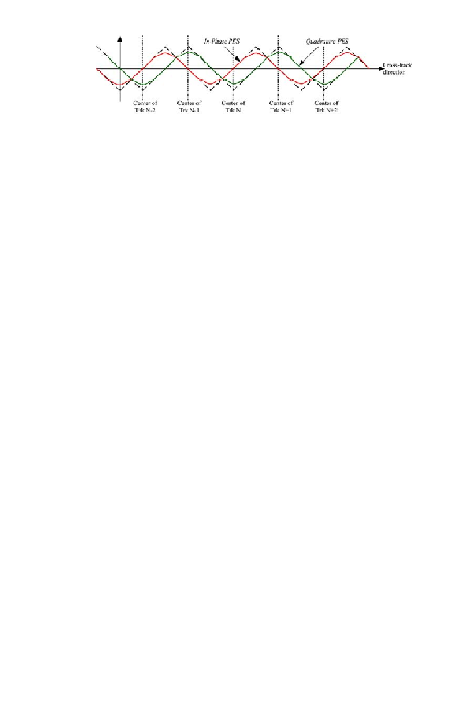
Figure 2.18: PES signal Vs off-track distance.
magnitude of PES
in−phase
.ThePES
in−phase
at different positions of the
head are shown using circles at the extreme right end of Figure 2.14. It also
showsaninterpolatedplotofPES
in−phase
versus cross-track displacement or
off-track position. It is easily understood that the PES
in−phase
signal has
alternating positive and negative slopes in adjacent tracks.
The plot shown in this illustration is obtained assuming ideal conditions
and it does not represent the PES
in−phase
in a drive. The dimension of the
read head is usually smaller than the width of a track, and if the head moves far
from the center of the track it senses flux emanating from only one of the two
bursts (either burst A or burst B) but not both. As a result, small movement
of the head around such position has no or little effect on the amplitudes of two
bursts. So the PES
in−phase
signal tends to saturate at large off-track distances,
as shown in Figure 2.18. This issue of nonlinearity in the measurement of off-
track displacement is resolved by creating a second pair of burst patterns, burst
C and burst D, placed in spatial quadrature with respect to the pair of burst
A and burst B, shown in Figure 2.14. The difference in amplitudes of these
two bursts (C and D) is called the quadrature PES signal,
PES
quad
= A
C
−A
D
.
(2.19)
A
C
and A
D
are the amplitudes of the waveforms of burst C and burst D,
respectively. The PES
quad
signal as a function of off-track error is also shown
in Figure 2.18. Its dependence on the off-track displacement is similar to that
of PES
in−phase
, but its zero-crossings coincide with the boundaries between
two adjacent tracks. Appropriate manipulation of in-phase and quadrature
PES signals produces an error signal proportional to the distance between
read head and the center of a track. The feedback signal used by the servo
loop is the combination of PES signal and track number obtained from the
grey code field.
In disk drives using embedded servo, the position feedback is available
only at discrete points in time and the servo control is also implemented in
discrete-time. However, the designer of servo controller is not at the liberty
of selecting the sampling frequency arbitrarily. The position signal is available
at a frequency S
N
disk
60
,whereS and N
disk
are the number of servo sectors per
track and rotational speed of disks in units of revolutions per minute or RPM,
respectively. The sampling frequency can be increased either by spinning the