Hardware Reference
In-Depth Information
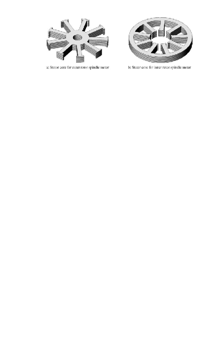
Figure 4.51: Laminated stator core of spindle motor: (a) stator core for outer
rotor spindle motor and (b) stator core for inner rotor spindle motor.
Since the bonded NdFeB magnet can produce strong magnetic
fi
eld, and
it is located in the gap between the stator core and rotor core, the armature
current does not have signi
fi
cant effect on the magnetic
fi
eld in the airgap.
Therefore, the dominant magnetic
fi
eld in the airgap is produced by the per-
manent magnet ring, even when the motor is in operation and the drive current
fl
ows. With this kind of EM structure, the armature reaction is weak, and the
inductances, including the self and mutual inductances, of the armature wind-
ings are small.
4.3.6 Stator Core
The stator core is used to form the required magnetic
fi
eld pass, or magnetic
circuit, on the motor stator, and is also the
fi
xture for the armature windings.
Figure 4.51 shows two typical stator cores. Compared to large AC motors,
there are few slots in stator core of the spindle motor. Since the dimensions
are small for the spindle motors, use of too many slots makes the teeth thinner.
This results in poor mechanical strength of the core. Moreover, production of
the stator core becomes difficult. Number of slots in typical HDD spindle
motors is 6, 9 or 12.
The magnetic pole-pair of spindle motor is usually more than 2 (see sec-
tion 4.2.4. Multiple magnetic pole-pair structure makes the frequency of the
stator magnetic
fi
eldbehighwhenthemotorisrotatingatitsratedspeed,and
eddy current is easily induced in the motor core. To reduce the eddy current,
the stator should be laminated with silicon steel sheets [69], [77].
4.3.7 Spindle Motor Bearings
Similar to the large motors, the ball bearing is a logical choice for the spindle
motor thanks to its low friction and high reliability. The structure of the ball
bearing used in HDD spindle is shown in Figure 4.52.