Hardware Reference
In-Depth Information
is determined by the winding pole-pairs,
F
a1
(θ)=F
p1
sin(pθ)=Ki
a
sin(pθ)
(4.32)
where, p is the pole-pair of the motor. The constant K is determined by the
turns and structure of the winding, and it can be obtained through Fourier
series analysis. If the winding current i varies with time as
i
a
(t)=I
m
sin(ωt)
(4.33)
where, ω is the angular frequency of the current. Then the MMF waveform of
equation 4.32 changes to
F
a1
(θ)=KI
m
sin(ωt)sin(pθ)=
KI
m
2
[cos(ωt −pθ) −cos(ωt + pθ)
(4.34)
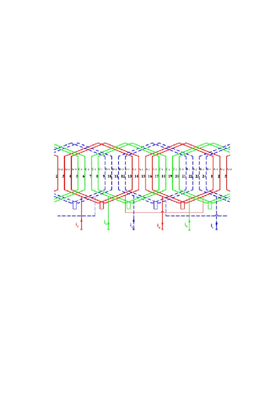
Figure 4.15: Three-phase distributed winding
Two other windings, B-phase winding and C-phase winding, can also be
installed on the stator to form a set of 3-phase symmetric windings in the
motor space. Figure 4.15 shows such 3-phase windings which is developed
from the 1-phase winding shown in Figure 4.14. It is clear, the fundamental
MMF harmonic of B-phase and C-phase windings can be expressed as
F
b1
(θ)=Ki
b
sin(pθ−120
◦
),
F
c1
(θ)=Ki
c
sin(pθ−240
◦
)
(4.35)
Moreover, if the currents i
b
and i
c
vary with time,
◦
i
b
(t)=I
m
sin(ωt −120
),
(4.36)
◦
i
c
(t)=I
m
sin(ωt −240
)