Hardware Reference
In-Depth Information
40
30
20
10
0
10
2
10
3
10
4
Frequency (rad/sec)
0
−30
−60
−90
10
2
10
3
10
4
Frequency (rad/sec)
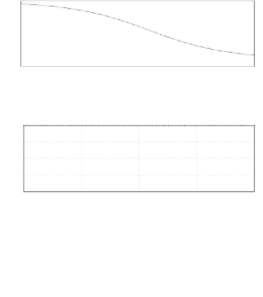
Figure 3.83: Frequency response of C
2
(s).
100
50
0
−50
−100
10
1
10
2
10
3
10
4
10
5
0
−50
−100
−150
−200
10
1
10
2
10
3
10
4
10
5
Freq. in Hz
Figure 3.84: Compensated plant P
SISO
(solid line). Dashed line: response of
C
1
(s)P
V
; Dash-dot line: response of C
2
P
M
.
transfer function T
dms
and the sensitivity transfer function S
dms
are defined
as
L
dms
=(1+C
M
P
M
)C
V
P
V
+ C
M
P
M
,
C
V
P
V
+ C
M
P
M
+ C
V
P
V
C
M
P
M
(1 + C
V
P
V
)(1 + C
M
P
M
)
T
dms
=
,
1
1+C
V
P
V
1
1+C
M
P
M
,
S
dms
=
(3.167)
respectively if none of the the actuators is saturated. Furthermore, S
dms
in
equation 3.167 is equivalent to the product of the following two transfer func-