Hardware Reference
In-Depth Information
100
50
0
−50
−100
10
0
10
1
10
2
10
3
10
4
10
5
10
6
0
−50
−100
−150
−200
10
0
10
1
10
2
10
3
10
4
10
5
10
6
Frequency (rad/s)
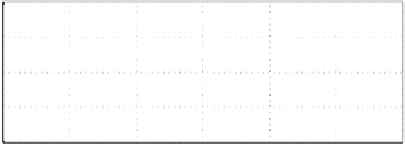
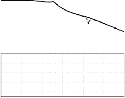
Figure 3.15: The Bode plot a rigid body actuator controlled by equation (3.11)
with (dashed line) and without (solid line) notch filter.
−130
−140
−150
−160
−170
−180
10
0
10
1
10
2
10
3
10
4
10
5
10
6
100
50
0
−50
10
0
10
1
10
2
10
3
10
4
10
5
10
6
Frequency (rad/s)
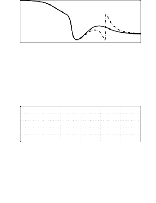
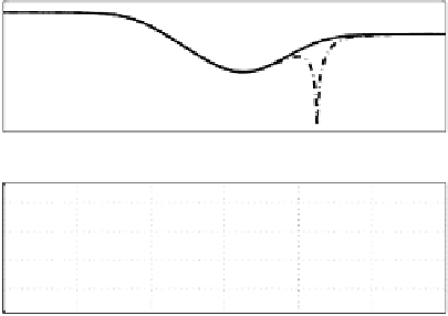
Figure 3.16: The Bode plot of the controller corresponding to Figure 3.15.
Similar to the case of adding notch filter for compensating actuator res-
onances, the stability and transient response of the closed-loop system need
to be checked after adding the sensor noise eliminating notch filter. This is
especially important when the notch frequency is close to the 0-dB cross-over
frequency.