Hardware Reference
In-Depth Information
40
35
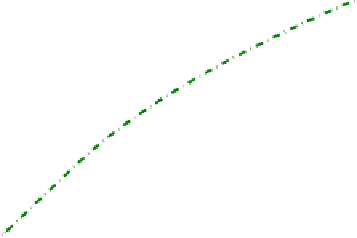
PTOS Velocity profile
30
25
20
15
10
5
Trajectory of the head slider
0
−5
−10
−20
0
20
40
60
80
100
Error (Tracks)
Figure 2.30: Phase plane for PTOS: Simulation result.
head velocity in tracks per sector, which is followed in the simulation results
shown. Position error for the 100-track seek is shown in Figure 2.31 with
a magnified scale so that settling behaviour of the seek is clearly seen. As
mentioned earlier, position error less than 10% or 15% of a track is considered
as the end of seek. For the simulation of 100-track seek, the error enters into
the band of ±10% at approximately 1.835 ms. Since the seek was initiated at
0.5 ms, time taken to complete a 100-track seek is approximately 1.335 ms.
Parameters of the PTOS controller are not designed optimally for the example
shown here. These simulation results are intended for an explanation of the
PTOS design, and the parameters are selected such that the linear controller
is applied for error less that 20 tracks, i.e., e
l
= 20.
The state feedback controller, which is used for the linear part of PTOS,
does not perform well in HDD during track following as it fails to reject the
effect of input disturbance. The input disturbance in VCM actuator originates
mainly from the flex cable. Rejection of such input disturbance requires high
gain at low frequency which can be realized using integral control. But the
linear part of the PTOS is PD (Proportional plus Derivative) control and does
not increase the low frequency gain substantially. But the input bias can be
estimated using an observer. It should be pointed out here that use of observer
is very much essential in HDD servomechanism as position is the only measured
state variable. The velocity of the read-write head slider, a variable required
by the seek control algorithm, must be estimated. Besides estimating the input
bias, its effect can also be cancelled by implementing a state feedback controller