Environmental Engineering Reference
In-Depth Information
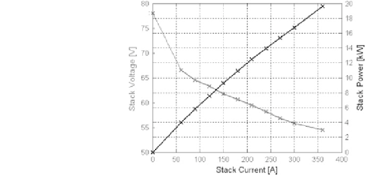
Fig. 7.3 Characteristic
curves of the 20 kW PEM
stack. Stack voltage and
power versus current at
T = 346 K and
P
air
= 250 kPa
The tests are run at the temperature of 346 K and reactant pressures of 250 kPa.
The air flow rate is set for each load value in order to assure the correct stack
operation and minimize air compressor power consumption and water flow rate
necessary for the humidification. This regulation of oxidant flow rate determines a
value of R ranging from 6 at low load to 2 at full load. An excess of air with
respect to the stoichiometric requirement is always necessary due to the mass
transport limitations on the cathode side (see
Sect. 4.3
). The stack humidification is
performed by saturating the inlet air stream at the temperature value approximately
equal to the measured one at the cathode outlet.
In Fig.
7.3
, the characteristic of the 20 kW PEM stack is reported in terms of
voltage and electric power as a function of stack current. The voltage versus
current diagram represents the polarization curve, which describes the stack
behavior for different loads (see
Sect. 3.3
). The stack output voltage decreases
from 78 V at open circuit to about 55 V at the highest load tested (360 A), while
the power increases with current and the highest power value (20 kW) is reached
at the current value of 360 A. It can be noted that in a wide range of load
conditions (60-300 A), the voltage is essentially linearly dependent on current,
indicating that the voltage drop in this range is mainly due to resistive losses. For
higher currents, a phenomenon of mass transfer limits the stack performance,
while the voltage drop observed at low loads is due to the slow activation of the
electro-catalysts (see
Sect. 3.3
).
In Figs.
7.4
and
7.5
, the voltages of the individual cells are reported for the
open circuit and full load, respectively. It can be noted that a rather uniform
distribution of voltage is obtained also in severe operative conditions when the
stack works at maximum power, with no endangering of the optimal stack
operation.
The different terms involved in the generation of power are reported in Fig.
7.6
as a function of stack current. In this figure, P
stack
is the electric power produced
by the stack, P
comp
is the power absorbed by the air supply device, P
pump
is the
power consumption of the cooling water pump, P
hum
is the power necessary to