Geology Reference
In-Depth Information
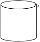
r
u
Δ
t
ρ
m
ρ
p
u
T
m
T
p
Figure 7.4. Idealised section of a plume, envisaged as a vertical cylinder.
heat can be calculated. The calculation is surprisingly direct, and requires few
assumptions about the plume material, other than that its buoyancy is due to heat,
rather than to composition.
7.2.1 Buoyancy transported by plumes
Consider material flowing up a plume conduit. Let us envisage the plume as a
vertical cylinder with radius
r
, as in Figure 7.4, so its cross-sectional area is π
r
2
.
Suppose the plume material flows upwards with an average velocity
u
. Within a
short time interval,
t
, the material will flow a distance
ut
. The volume of fluid
that has flowed past a point, say at the bottom of the plume section shown, is then
V
π
r
2
ut
.Now,dividingby
t
,the
volumetric flow rate
is
φ
=
=
V/t
,inother
words the volume per unit time flowing past a point:
π
r
2
u.
φ
=
(7.1)
Buoyancy, as we saw in Chapter 5, is the gravitational force due to the density
deficit of the buoyant material. The buoyancy of the material in the cylinder section
shown in Figure 7.4 is
B
=
gρV,
where
ρ
(
ρ
m
−
ρ
p
) is the density difference between the plume and the
surrounding mantle. This is the buoyancy of the material that has flowed up the
plume in the time interval
t
.Ifwedivide
B
by
t
we can get the
rate
,
b
,atwhich
buoyancy is flowing up the plume conduit:
=
gρ
π
r
2
u.
b
=
(7.2)
This establishes the idea of a buoyancy flow rate in an idealised plume conduit. It
can be related to hotspot swells, which we will now do.
The way buoyancy flow rate can be inferred from hotspot swells is clearest in
the case of Hawaii. The Hawaiian situation is sketched in Figure 7.5, which shows
a map view (left) and two cross-sections. As the Pacific plate moves over the rising
column of plume material, it is lifted by the plume buoyancy. The weight of the
excess topography created by this uplift exerts a downward force, and the buoyancy