Environmental Engineering Reference
In-Depth Information
or so from the time of writing, PV systems will be providing a sizeable proportion of the
renewable energy contribution.
Some countries, notably Japan and Germany, have created substantial home based markets
for PV cells, and the last couple of years have seen a rapid growth in multimegawatt instal-
lations in Europe. Despite this encouraging trend, the relatively high present cost of PV
systems are likely to limit them to modest contributions to overall electricity supply in
the immediate future. In sunnier places such as California, Australia, North Africa and the
Mediterranean, where the peak electricity demand occurs in summer due to tourism and
air-conditioning loads, large scale multimegawatt PV plants or solar thermal plants are
more attractive. Nevertheless, signifi cant technology and cost breakthroughs in these two
solar technologies will be needed if they are to make sizeable contributions to electricity
supply.
The characteristics of PV and solar thermal plants are rather different and are next
outlined.
2.5.3 Photovoltaic Systems
At the heart of a PV system is the PV module. Detailed descriptions of the different PV
technologies and the basics of solar cell operation can be found in a wide range of textbooks,
for example References [13] and [14]. PV modules produce output determined mainly by the
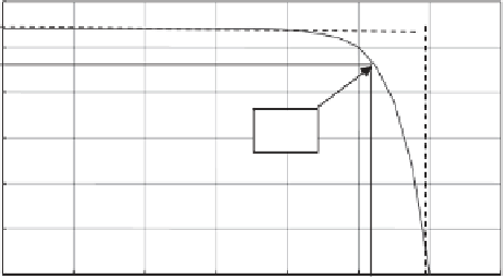
level of incident radiation. They are characterized for given external conditions, by an
I - V
curve of the type shown in Figure 2.13. The power,
IV
, depends on the operating point and
is maximized for operation near to the knee of the
I - V
characteristic, known as the maximum
power point (MPP). Power electronics is used to convert the DC (direct current) output of
the PV modules to AC (alternating current) for injection into the network (more about this
in Chapter 3). The quality of a cell can be judged by the squareness of the
I - V
characteristic.
This is quantifi ed in terms of the ratio of the voltage at open circuit (i.e. where the
I - V
curve
meets the voltage axis) times the closed circuit current (i.e. where the
I - V
curve meets the
current axis), divided by the power at the MPP. This ratio is known as the fi ll factor.
3
2.5
2
MPP
1.5
1
0.5
0
0
0.1
0.2
0.3
0.4
0.5
0.6
0.7
Voltage (Volts)
Figure 2.13
An example
I - V
curve