Environmental Engineering Reference
In-Depth Information
+
Q
Generators of
P
Consumers of
Q
Consumers of
P
of
Q
v
-
P
+
P
I
Consumers of
P
Generators of
P
and
Q
Generators of
Q
-
Q
Figure A.18
Quadrant diagram
Q
=
I
2
X
Z
X
V
=
IZ
V
X
=
IX
S
=
VI
=
I
2
Z
=
VI sin
q
q
q
q
I
R
V
R
=
IR
P
=
I
2
R
=
VI cos
q
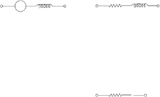
(a) Impedance triangle
(b) Phasor diagram
(c) Power triangle
Figure A.19
The complex power triangle
phasorial addition of the voltage
V
R
across the resistor (in phase with the current) and voltage
V
X
across the reactor (in quadrature and leading the current). If the magnitude of each voltage
phasor is divided by
I
a similar triangle, the
impedance triangle
, is obtained, shown in Figure
A.19(a). If each voltage magnitude is multiplied by
I
, another similar triangle, the
power tri-
angle
, is obtained, shown in Figure A.19(c). The hypotenuse of this triangle is of course the
apparent power seen earlier. The apparent power
S
in VA can be visualized as a complex
quantity with a real component
P = VI
cos
θ
in watts and an imaginary component
Q = VI
sin
θ
in VAR. The complex power
S
is therefore defi ned as
S
=
VI
cos
θ
+
j
VI
sin
θ
=
P
+
j
Q
(A.27)
Note that the power factor angle
is the same angle in all three triangles.
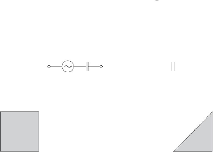
Now the complex power is ready to be derived directly from the applied voltage and the
resulting current in a circuit element. In the element of Figure A.20 the phasors of voltage
and current can be expressed in general by the exponential form
θ
j
α
j
β
V
AB
=
V
e
and
I
=
I
e
AB
AB
AB