Environmental Engineering Reference
In-Depth Information
A.9.3 Capacitance
Dividing Equation (A.14) by (A.15) ,
V
I
∠
∠
0
90
°
°
V
VC
∠
∠
0
°
Opposition offered by capacitance
=
=
ω
90
°
1
=∠
0
°°−90°=
X
∠−
90
°=−
j
X
ohm
(A.20)
C
C
ω
C
The quantity
fC
) is known as
capacitive reactance
and represents the
' opposition ' to the fl ow of current when a voltage of frequency
f
Hz is applied across a
capacitance of
C
farad. Again the 90 ° phase lead to the current is conveniently incorporated
in the
−
j
X
C
=
−
j/(
ω
C
) =
−
j/(2
π
−
j operator of the reactance expression.
A.9.4 Impedance
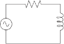
Now two components will be connected in series and the effects will be investigated. Take,
for example, the circuit in Figure A.16.
The resistor will offer 5
Ω
of resistance to AC current regardless of frequency, while the
inductor will offer
2
of reactance to AC current at 50 Hz. Because the resistor's
resistance is a real number (10 + j0
π
fL
= 6.282
Ω
Ω
) and the inductor's reactance is an imaginary number
(0 + j6.282
), the combined effect of the two components will be an opposition to current
equal to the complex sum of the two numbers. In order to express this opposition succinctly,
a more comprehensive term is needed for opposition to the current than either resistance
or reactance alone. This term is a complex number known as
impedance
Z
, and is also
given in ohms, just like resistance and reactance. In the above example, the total circuit
impedance is
Ω
(
)
++
(
)
=+
Z
=+
10
j
0
0
j6.282
10
j6.282 or
11 81
.
∠
32 137
.
°
Impedance is related to voltage and current in a manner similar to resistance in Ohm's law:
(A.21)
VIZ
=
where all the quantities are expressed in complex form.
5
Ω
10 V
50 Hz
20 henry
Figure A.16
Series AC circuit