Environmental Engineering Reference
In-Depth Information
direction of current. It is concluded that to calculate the power in a purely resistive element
any of the following expressions can be used:
2
V
R
P
== =
RI
2
VI
(A.7)
A.5.2 Inductance
Inductors do not behave like resistors. Whereas resistors simply oppose the fl ow of electrons
through them (by dropping a voltage directly proportional to the current), inductors oppose
changes
in current through them, by dropping a voltage directly proportional to the
rate of
change
of the current.
Ohm's law for an inductance
L
in henries is the following differential rather than linear
relationship:
vL
i
t
d
d
=
(A.8)
=
sin
Assume that a sinusoidal current
iI
fl ows through an inductor of inductance
L
. Inserting this in the r.h.s. of Equation (A.8) gives
v
ω
t
=
(
)
, where
ω
LI
cos
ω
t
=
V t
cos
ω
(A.9)
=
(
)
VLI
ω
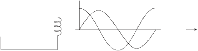
Figure A.6 shows the voltage/current relationship for an inductor. The voltage represented
by the cosine curve is 90 ° ahead of the current sine curve. The voltage is now said to
lead
the current by 90 ° or the current to
lag
the voltage by the same amount. In general, if two
AC waveforms are phase-shifted by 90 °, it is said that these waveforms are in
quadrature
to each other. If the voltage is described by
=
sin
(A.10)
vV
ω
t
sin
(
)
then the current would take the form
iI
=
ω
t
−
π
2
, which through Equation (A.9)
becomes
V
L
2
⎛
⎝
⎞
⎠
i
=
sin
ω
t
−
(A.11)
ω
i
v
i
v
L
Time
Figure A.6
Inductor excited by AC voltage