Environmental Engineering Reference
In-Depth Information
V
i
V
i
V
x
V
x
θ
V
o
I
o
V
o
I
o
(a)
(b)
Figure 4.34
Phasor diagrams of the output stage of a grid-connected inverter; (a) general case and
(b) at unity power factor
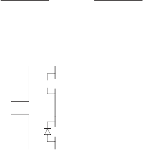
DC
AC
Figure 4.35
Three - phase IGBT bridge
VI
=
VI
cos
φ
dc
dc
o
o
where
I
dc
is the average value of the current drawn from the DC source. Thus, by using the
PWM pattern to control the output, the input current has been controlled.
The Three - phase Bridge
All of the preceding circuits and discussions may readily be extended to three-phase systems.
Usually this requires only an additional 50% of devices as shown in Figure 4.35 where a
single-phase bridge with four transistors has becomes a three-phase bridge with six transis-
tors. Inverters above 10 kVA are usually three-phase.
Three-phase power electronic converters are extensively used in variable speed wind tur-
bines to convert AC to DC and vice versa. The circuit shown in Figure 4.35 is known vari-
ously as a transistor bridge, an inverter, a voltage-source converter, a variable frequency drive
or just about any combination of those words. It is widely used throughout industry to operate
induction motors at variable speed. IGBT converters are expensive, typically several times
the cost of the associated electrical machine.