Environmental Engineering Reference
In-Depth Information
ω
—
Slip
2.0
-1.0
1.8
-0.8
Max
torque
Rated
torque
1.6
-0.6
Rr˝>Rr´
1.4
-0.4
Rr´>Rr
1.2
-0.2
Rr
1
0
0
0.5
1.0 1.5
Torque Q/QR
2.0
2.5
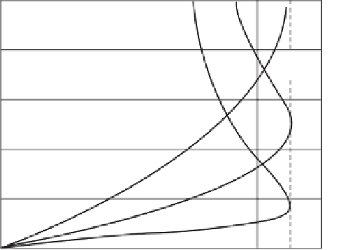
Figure 4.16
Normalized speed and slip against torque for a generator
2
3
Vs
R
s
Q
≈
(4.28)
m
ω
Equation (4.28) indicates that in the normal operating range (zero to rated torque), torque
is directly proportional to slip and therefore speed and is inversely proportional to
R
r
. Curves
for
RR
sr
′′
>
r r
are also plotted on Figure 4.16. By selecting the value of the rotor
resistance, a designer has the ability to change the slope of the torque-speed characteristic.
If a substantial variation of speed with torque is required, the rotor can be designed to have
a large resistance. The downside of such an arrangement is the unacceptable reduction in
effi ciency.
A method to access the rotor windings and therefore exploit the property of speed change
is to arrange a rotor that has coils rather than short circuited bars, with the coil terminals
connected to slip rings and brushes so that additional external resistance can be connected in
series with the windings. In such a
rotor wound
induction machine, the rotor winding is
similar to that on the stator. The disadvantages of the wound rotor induction generator include
a higher capital cost and a higher maintenance cost.
′
>
r
and
RR
r
Worked Example 4.3
A wind turbine rated at 450 kW has the following induction generator parameters in ohms:
R
s
= 0.01,
X
s
=
X
r
= 0.15,
R
r
= 0.01 and
X
m
= 6. At a time when it is supplying its rated output
the slip is 0.01. Calculate the mains voltage and the power factor at which the induction
generator is supplying power to the grid using the simplifi ed equivalent circuit.