Environmental Engineering Reference
In-Depth Information
that the mechanical input power is converted into electrical power with maximum effi ciency
and with minimum cost of materials.
Up to this point the alternator in standalone mode has been considered. The rotor driven
by a prime mover induces a set of balanced three-phase voltages in the stator windings, as
shown in Figure 4.2(b). If a balanced three-phase load is connected across the windings, a
balanced set of currents will transfer power from the prime mover to the load. This standalone
operation is the exception rather than the rule in power generation. Rather, the alternator is
most likely to be required to inject power into a grid that to all intents and purposes may be
considered an
infi nite bus
. This mode of operation is discussed in the following sections.
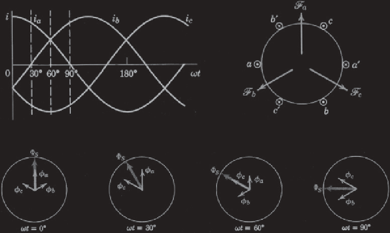
4.2.2 The Rotating Magnetic Field
An examination will fi rst be made of what happens when the primitive stator windings of
Figure 4.2(a) are connected to a three-phase supply and the rotor is absent. Figure 4.4(a)
shows the balanced currents that will be drawn by the three primitive windings which are
redrawn in Figure 4.4(b) [1]. When stator winding
aa
carries the sinusoidal current
i
a
, Equa-
tion (4.2) tells us that
i
a
will generate a sinusoidally pulsating space vector fi eld
F
a
and
therefore a fl ux
′
in Figure 4.4 (b).
Similarly, the remaining two currents
i
b
and
i
c
in Figure 4.4(a) will generate pulsating fi elds
and fl uxes
F
b
,
φ
a
along the axis of coil
aa
′
φ
b
and
F
c
,
φ
c
along the axes of coils
bb
′
and
cc
′
respectively. Positive currents
in the windings fl owing into the
⊗
conductor and returning through the
conductor in each
(a)
(b)
(c)
Figure 4.4
Production of a rotating magnetic fi eld. (Reproduced from Reference [1] with permission
of John Wiley & Sons, Inc.)