Environmental Engineering Reference
In-Depth Information
c
b
´
V
a
´
a
V
b
´
b
V
c
´
c
v
N
0
120°
240°
360°
a
´
a
S
c
´
b
(a)
(b)
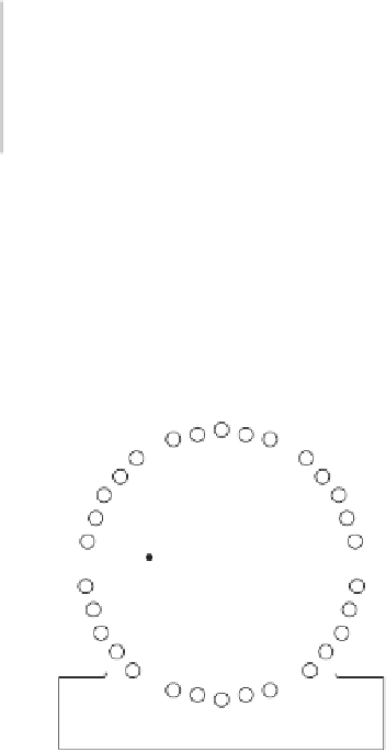
Figure 4.2
A primitive three -phase synchronous generator
a
b
´
c
´
N
ω
I
f
S
c
b
a
´
Figure 4.3
A practical three -phase synchronous generator
The peripheral velocity with which the conductors in the embedded windings cut the
magnetic fl ux is, of course, proportional to the angular velocity
. Using Equations (4.1) and
(4.2), the induced voltage
V
generated in a stator winding for a rotating generator is therefore
given approximately by:
ω
VkI
=
ω
f
(4.3)
where
k
is a constant of proportionality that depends on the number of turns in each winding,
the distribution of the conductors in the slots, the length of the air gap and the general geom-
etry and magnetic properties of the iron that carries the magnetic fl ux. Electrical machine
designers take all of these factors into account when designing synchronous generators so