Database Reference
In-Depth Information
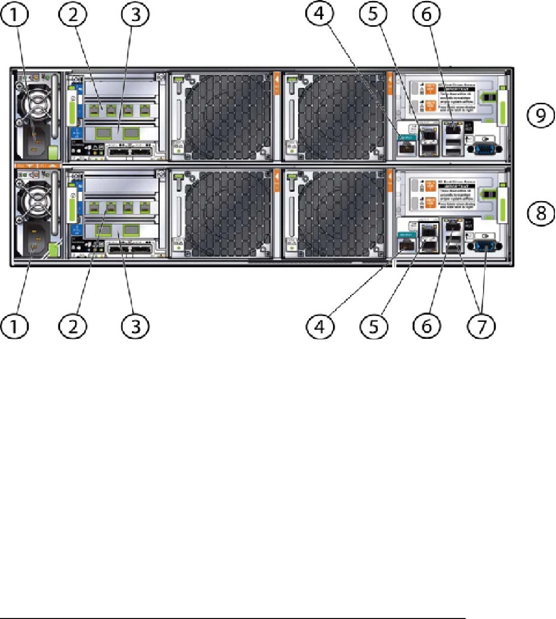
Figure 3-1.
Network and other connections on the back of the original ODA
Table 3-1.
Descriptions of the Connections Highlighted in Figure
3-1
Callout
Description
1
C13 Power Connectors, shared power bus for both nodes
2
eth4, eth5, eth6, and eth7 from right to left for Node 0; eth4 and eth5 are bond1 and
eth6 and eth7 are bond2
3
10BaseT SFP ports for eth8 and eth9 for Node 0, configured as xbond0
4
ILOM Serial Port for Node 0
5
eth2 and eth3, bond0 for public network access
6
ILOM 10/100 BaseT port
7
USB and VGA ports
8
Node 0
9
Node 1