Environmental Engineering Reference
In-Depth Information
J
g
is the gas superficial velocity (gas volumetric flow rate divided by column cross-
sectional area, m/s). Typically, the Sauter mean diameter (
D
32
)isused.
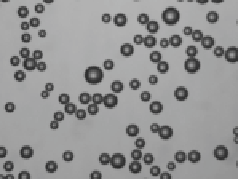
However, industrial bubbling devices produce a rather broad BSD, making the
use of a single mean diameter inaccurate, since the same value could be obtained
from quite different size distributions. This point will be discussed in Section 6.3.
Recent studies made by Gorain
et al.
[8] have shown that flotation performance,
expressed in terms of the flotation kinetic constant, is strongly related to bubble sur-
face area flux. It was demonstrated that neither the bubble size, nor the gas hold-up,
nor the gas superficial velocity, independently considered, could adequately corre-
late to the kinetic constant. On the other hand, it was shown that the bubble surface
area flux exhibited a linear relation with the kinetic constant, at various impeller
speeds. Similar results were later reported by other researchers [9, 10]. Although
S
b
seems a potential control variable to achieve a given metallurgical performance,
its present definition disregards important information related to the shape of the
BSD, such as multi-modal, narrowness and tail properties. Therefore, formal con-
trol strategies should take into account the
S
b
value in conjunction with the shape of
the BSD. This issue will be discussed in Section 6.5. Controlling the bubble diame-
ter implies manipulating some key variables, such as the gas superficial velocity, the
frother concentration, and in some cases the bubble generator (either the pore size
for laboratory porous spargers, or the output orifice size in the case of some commer-
600
400
200
0
0
0.5
1
1.5
2
(a)
bubble diameter (mm)
(b)
Figure 6.2
(a) Picture of laboratory column bubbles. (b) Histogram representation of bubble size
Figure 6.3
Bubble surface area flux concept


Search WWH ::

Custom Search