Environmental Engineering Reference
In-Depth Information
log
10
d
50
(
c
)=
k
1
v
f
−
k
2
Spig
+
k
3
In
+
k
4
c
−
k
5
q
s
+
k
6
,
(5.28)
where
v
f
is the vortex diameter,
Spig
is the spigot diameter,
In
is the inlet diameter,
c
is the feed percentage of solids, and
q
s
is the slurry volumetric flowrate.
The water balance is
q
u
=
q
f
−
r
f
q
f
,
(5.29)
where
r
f
is the percentage of water in the underflow, which has been correlated with
inlet volumetric flowrate
w
f
and spigot diameter
Spig
as follows:
k
7
Spig
w
f
1
w
f
+
=
−
.
r
f
k
8
k
9
(5.30)
All of the parameters
k
i
9 can be adjusted so as to model a specific hydro-
cyclone. The ore hardness of the feed is transferred to the over and underflows.
,
i
=
1
, ...,
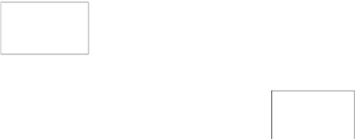
5.4.4 Sump
The sump can be modeled as a perfect mixed tank, due to its relatively small size
and the turbulence produced by the feed flow. Thus, a model for a perfect mixing
tank is considered [11]. The main input and output variables are depicted in Figure
5.9.
feed
Flowrate
Water flowrate
Size distribution
Hardness
f
q
f
f
γ
f
output
p
q
p
p
γ
Flowrate
Water flowrate
Size distribution
Hardness
Figure 5.9
Asump
Under the assumption that no change in particle size occurs in the sump, the
following mass balance equation provides a description of mass size distribution in
the sump:
d
m
(
t
)
=
f
(
t
)−
p
(
t
)
m
(
t
).
(5.31)
dt
p
represents the mass rate of solids discharged from the sump. Sump level varia-
tions can be found by combining a volumetric balance of slurry and solid balance:
(
t
)


Search WWH ::

Custom Search