Environmental Engineering Reference
In-Depth Information
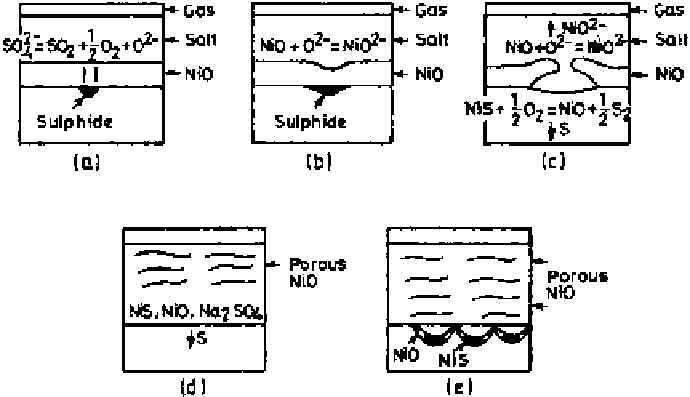
Figure 6.38
Schematic diagram illustrating the sequential development of scale in
Na
2
SO
4
-induced hot corrosion of pure Ni in 1 atm O
2
[16].
into the metal. Repetition of this process eventually produces a porous, honey-
comb-like NiO layer (Fig. 6.38d) and results in diffusion of sulfur and oxygen
along the grain boundaries of the metal (Fig. 6.38e). Eventually as Na
2
SO
4
is
trapped in the porous scale, the rapid reaction ceases, leading to the formation
of a dense protective NiO layer. The reaction path followed in molten Na
2
SO
4
is illustrated in Fig. 6.39 by superimposing the stability diagram of the Ni-S-O
system onto the stability region of the Na-S-O system.
A similar basic fluxing mode of attack is also observed for protective oxides
such as Cr
2
O
3
and Al
2
O
3
(usually formed on high-temperature alloys) as in the
hot corrosion of Ni-8% Cr-6% Al alloy [58]. Initial formation of Cr
2
O
3
and Al
2
O
3
depletes the molten salt of oxygen and lowers the oxygen potential, creating an
oxygen gradient across the melt. As a result of this gradient in oxygen pressure,
the sulfur activity increases and nickel sulfide is formed at the surface of the
alloy. The low sulfur and oxygen potentials of the salt due to formation of oxides
and sulfides lead to an increase in the oxide ion or Na
2
O activity in the melt,
reaching values at which Al
2
O
3
and Cr
2
O
3
can dissolve. A process is therefore
developed whereby sulfate ions diffuse toward the alloy, and as a region of lower
oxygen pressure is approached, these ions sulfidize nickel whereupon oxide ions
are produced. These in turn react with Al
2
O
3
and Cr
2
O
3
to form soluble products
in oxide ion-enriched Na
2
SO
4
.