Geology Reference
In-Depth Information
3
aglyF
3
aglyF
j
i
,
k
k
j
=
,
i
J
12
*
12
*
If
n
i
fractures intersect fracture
i
, then the time dependent mass
conservation equation for fracture
i
is given by:
I
K
n
dh
QVS
dt
i
i
)
y
i
i
j
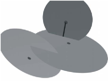
Figure 2.
Geometry of the fracture network
underlying the fluid flow law.
The fracture volume term
V
i
(m
3
) is:
V
i
=
R
i
2
and the specific storage of the
S
i
(m
-1
) is a constant or, under unsaturated
condition, a function of the water content:
g
a
-+
S
i
=
(5)
-,
where
R
i
is the fracture radius (m) and is the fluid density (kgm
-3
).
In deriving the specific storage term, the rock stress has been assumed
constant, such that changes are caused only by fluid pressure changes. Also,
fluid compressibility is generally much smaller than fracture compressibility
and, thus, has been neglected. The form of the term
d
, calculated at the
centre of the fracture disc, depends on the assumed form of the relationship
between the pore pressure and the water content that we use to describe the
material infilling the fractures.
+
/
d
,
Modelling the Slug Tests Using the FRACAS DFN Approach
The objective of this section is to identify and calibrate a set of parameters
suitable for modelling the observed spatial variability of the slug test responses,
described in Fig. 1. Our working assumption is that the variability of the
numerical responses resulting from statistically equi-consistent alternatives
of the fracture network should be similar to the variability observed on the
field. Therefore, our strategy will be (i) to built a set of fracture networks,
using the same geometrical characteristics, (ii) simulate a transient hydraulic
test, similar to a slug test, in each one of these networks and (iii) analyse the
set of responses in terms of mean behaviour and deviation between the
tested alternatives. This should be comparable with the in-situ corresponding
curves in Fig. 1.